3A-10 Drive Shaft / Axle:
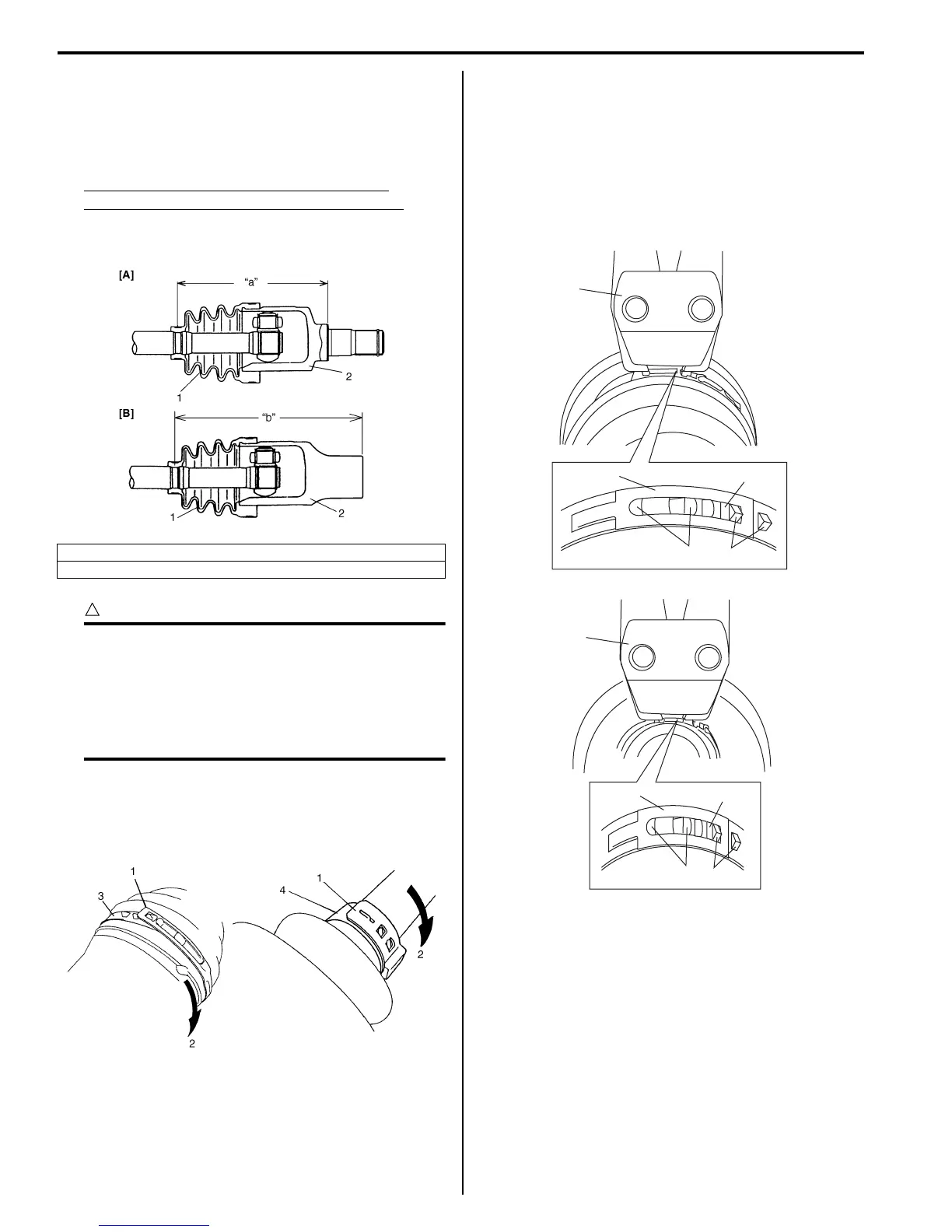
11) Fit boot (1) to grooves of shaft and housing (2) adjust
length to specification below.
12) Insert screw driver into boot and allow air to enter
boot so that air pressure in boot becomes the same
as atmospheric pressure.
Drive shaft boot fixing position (distance
between housing end and small boot band)
Left side drive shaft “a”: 153.9 mm (6.05 in.)
Right side drive shaft “b”: 178.0 mm (7.00 in.)
CAUTION
!
• Bend each boot band against forward
rotation.
• Do not squeeze or distort boot when
fastening it with bands. Distorted boot
caused by squeezing air may reduce its
durability.
13) Place differential side (or center shaft side) boot new
big band (3) and new small band (4) onto boot
putting band outer end (1) against forward rotation
(2) as shown in figure.
14) Fasten differential side (or center shaft side) boot
band.
• For differential side (or center shaft side) boot big
band (1) and small band (5).
Fasten band by drawing hooks (2) with special
tool and engage hooks (3) in slot and window (4).
Special tool
(A): 09943–57021
[A]: Drive shaft inserted into differential side
[B]: Drive shaft inserted into center shaft side
I4RS0B310004-01
I5JB0A311006-01
(A)
1
4
2
3
(A)
5
4
2
3
I6RS0B310005-02
 Loading...


