Engine General Information and Diagnosis: 1A-5
Freeze frame data clearance:
The freeze frame data is cleared at the same time as
clearance of DTC.
Non-Euro-OBD
ECM diagnosis troubles which may occur in the area
including the following parts when the ignition switch is
ON and the engine is running, and indicates the result by
turning on or flashing malfunction indicator lamp (1).
• Heated oxygen sensor
• ECT sensor
•TP sensor
• APP sensor
• MAF sensor
• IAT sensor
• MAP sensor
• CMP sensor
• CKP sensor
• Knock sensor
• Wheel speed sensor (VSS)
• CPU (Central Processing Unit) of ECM
• Oil control valve
• EGR valve
• EVAP canister purge valve
• Ignition coil
• Starter relay
• Radiator fan relay
• CAN communication
• Barometric pressure sensor
• ECM back up power supply
ECM and malfunction indicator lamp (1) operate as
follows.
• Malfunction indicator lamp (1) lights when the ignition
switch is turned ON (but the engine at stop) with the
diagnosis switch terminal ungrounded regardless of
the condition of Engine and Emission control system.
This is only to check the malfunction indicator lamp (1)
in the combination meter and its circuit.
• If the above areas of Engine and Emission control
system is free from any trouble after the engine start
(while engine is running), malfunction indicator lamp
(1) turns OFF.
• When ECM detects a trouble which has occurred in
the above areas, it makes malfunction indicator lamp
(1) turn ON while the engine is running to warn the
driver of such occurrence of trouble and at the same
time it stores the trouble area in ECM back-up
memory. (The memory is kept as it is even if the
trouble was only temporary and disappeared
immediately. And it is not erased unless the power to
ECM is shut off for specified time or it is cleared by
SUZUKI scan tool (2).)
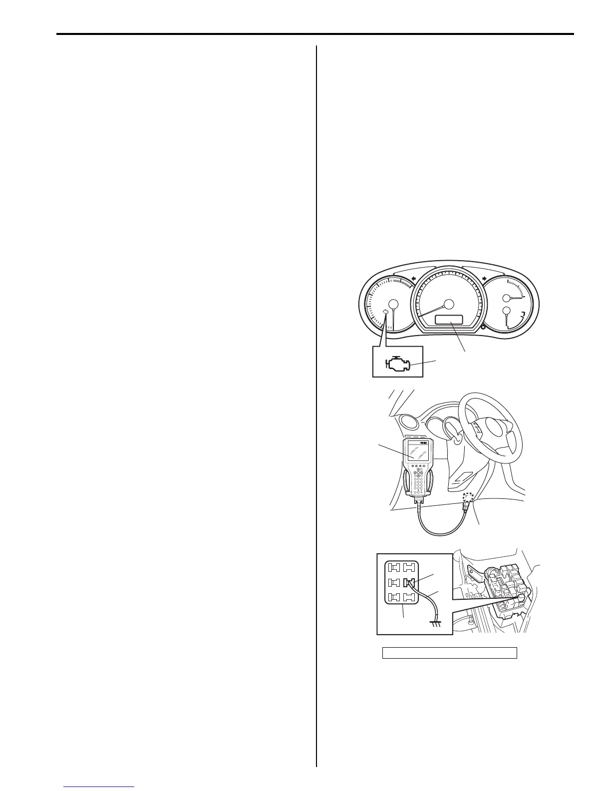
For Hong Kong model, DTC can be read by not only
using SUZUKI scan tool but also displayed on
odometer (5) of the combination meter. (i.e. when
diagnosis switch terminal (3) is grounded with a
service wire (4) and ignition switch is turned ON.) For
further detail of the checking procedure, refer to “DTC
Check”.
6. Diagnosis connector
2
1
6
3
5
4
I5RS0C110021-01
 Loading...


