4E-11 ABS:
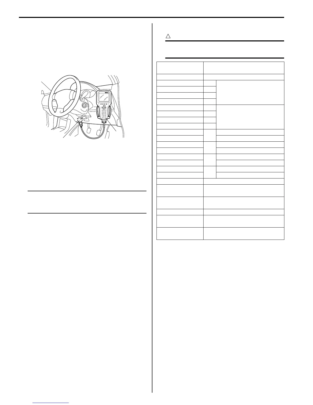
DTC Check
S7RS0B4504004
1) Turn ignition switch to OFF position.
2) Connect SUZUKI scan tool to data link connector
(1).
Special tool
(A): SUZUKI scan tool
3) Turn ignition switch to ON position.
4) Read DTC according to instructions displayed on
SUZUKI scan tool and print it or write it down. Refer
to SUZUKI scan tool operator’s manual for further
details.
NOTE
If SUZUKI scan tool can not communicate
ABS hydraulic unit / control module, perform
“Serial Data Link Circuit Check”.
5) After completing the check, turn ignition switch off
and disconnect SUZUKI scan tool from DLC.
DTC Table
S7RS0B4504005
CAUTION
!
Be sure to perform “ABS Check” before
starting diagnosis.
1
(A)
I4RS0A450009-01
DTC (displayed on
SUZUKI scan tool)
Diagnostic Items
NO DTC Normal
)C1021 RF
Wheel speed sensor circuit
)C1025 LF
)C1031 RR
)C1035 LR
)C1022 RF
Wheel speed sensor circuit
or sensor ring
)C1026 LF
)C1032 RR
)C1036 LR
)C1041
RF
Inlet solenoid valve circuit
)C1042 Outlet solenoid valve circuit
)C1045
LF
Inlet solenoid valve circuit
)C1046 Outlet solenoid valve circuit
)C1051
RR
Inlet solenoid valve circuit
)C1052 Outlet solenoid valve circuit
)C1055
LR
Inlet solenoid valve circuit
)C1056 Outlet solenoid valve circuit
)C1057 Power source
)C1061
ABS pump motor and/or motor
driver circuit
)C1063
Solenoid valve power supply driver
circuit
)C1071 ABS control module
)U1073
Control Module Communication
Bus Off
)U1100
Lost Communication with ECM
(Reception error)
 Loading...


