ABS: 4E-20
DTC C1041 / C1045 / C1051 / C1055, DTC C1042 / C1046 / C1052 / C1056: Right-Front / Left-Front /
Right-Rear / Left-Rear Inlet Solenoid Circuit, Right-Front / Left-Front / Right-Rear / Left-Rear Outlet
Solenoid Circuit
S7RS0B4504013
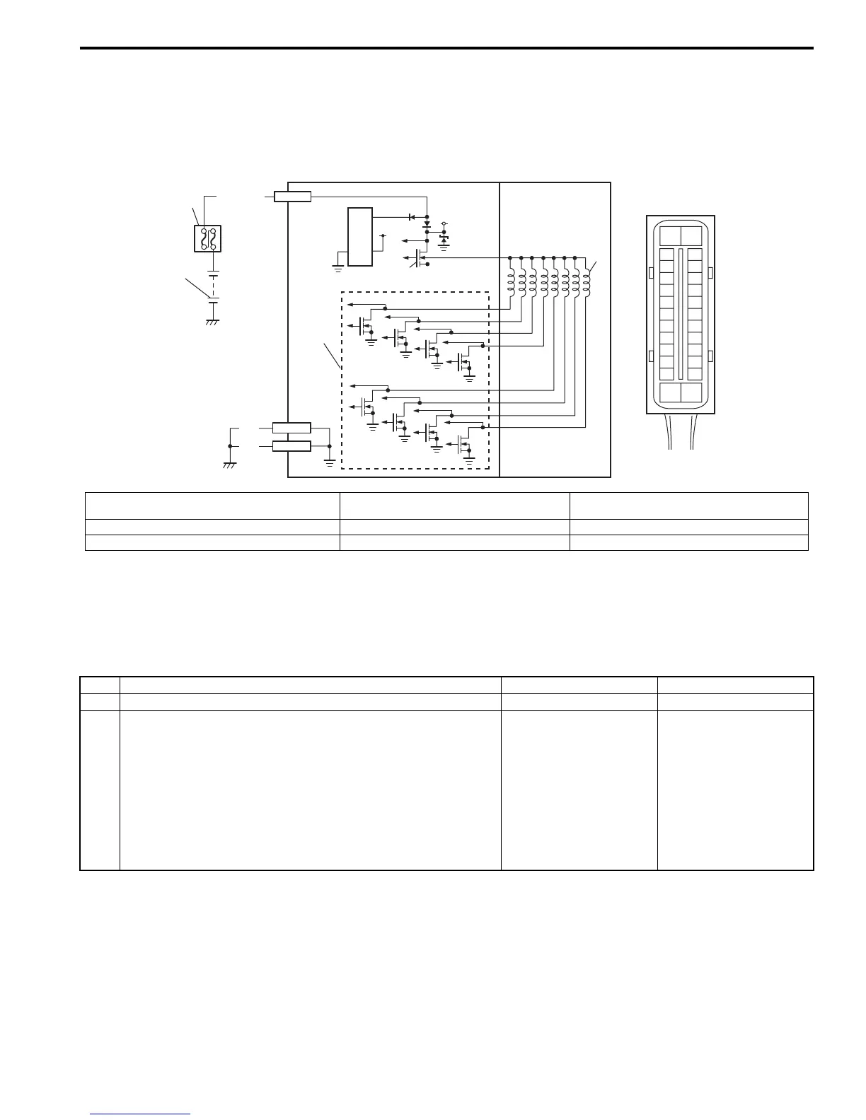
Wiring Diagram
DTC Detecting Condition
The ABS control module monitors the output from the valve.
When the output of each valve exceeds the specified value compared with the signal sent from ABS control module,
this DTC is set.
DTC Troubleshooting
6
4
E03-14
5V
12V
7
3
WHT/BLU
1
2
5
BLK
BLK
E03-13
E03-26
[A]
E03
15
16
17
18
19
20
21
22
23
24
25
2
3
4
5
6
7
8
9
10
11
12
1
13
14
26
I6RS0C450010-01
[A]: ABS hydraulic unit / control module assembly
connector (viewed from terminal side)
3. ABS power control module 6. Solenoid valve power supply driver (transistor)
1. Battery 4. Solenoid valve 7. Solenoid valve driver (transistor)
2. Main fuse box 5. ABS hydraulic unit / control module assembly
Step Action Yes No
1 Was “ABS Check” performed? Go to Step 2. Go to “ABS Check”.
2 1) Turn ignition switch to OFF position.
2) Disconnect ABS hydraulic unit / control module
connector.
3) Check for proper connection to ABS hydraulic unit /
control module connector at terminal “E03-14”.
4) If OK, then measure voltage between terminal “E03-14”
of module connector and “E03-26”.
Is it 10 – 14 V?
Substitute a known-
good ABS hydraulic unit
/ control module
assembly and recheck.
“WHT/BLU” or “BLK”
circuit open.
 Loading...


