Electronic Stability Program: 4F-49
DTC U1073: Control Module Communication Bus Off
S7RS0B4604057
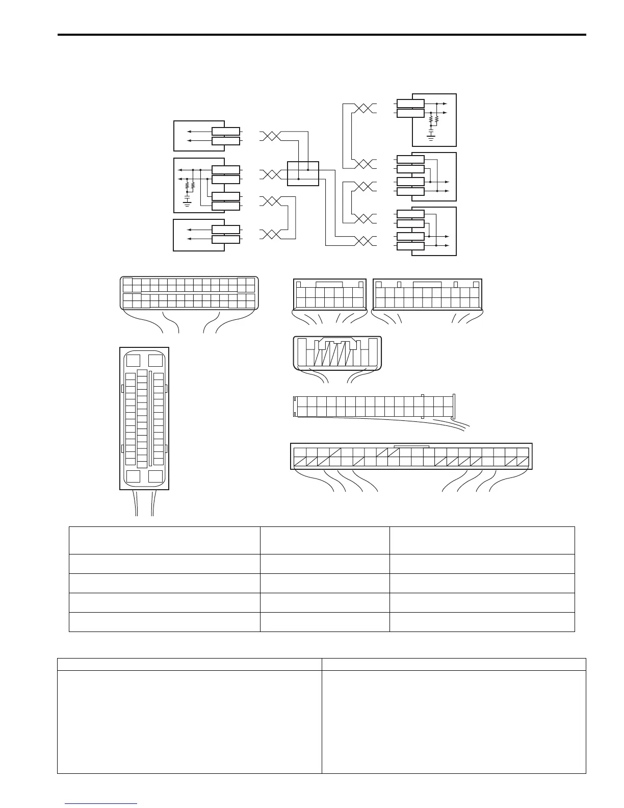
Wiring Diagram
DTC Detecting Condition and Trouble Area
E85-13
E85-44
E46-2
E46-1
G37-4
G37-2
E85-46
E85-42
E23-3
E23-18
G50-9
G50-10
G28-8
G28-10
G28-9
G28-7
G42-19
G42-18
RED
WHT
WHT
RED
WHT
RED
RED
WHT
RED
WHT
WHT
RED
RED
WHT
RED
WHT
RED
WHT
[A]
21
E23
34
1819
5671011
17
20
47 46
495051
2122
52
16
25
9
24
14
29
5557 5453
59
60
58
26
27
28
15
30
56
48
32 31343536374042 3938
44
45 43 41 33
1213
23
8
G42
[F]
1234567891011141516
36 34 33 32 31 30 29 24 2337
181920
[B]
E85
16
1
15
2
3
4
5
6
7
8
9
10
11
12
13
14
17
18
19
20
21
22
23
24
25
26
27
28
29
30
31
32
33
34
35
36
37
38
39
40
41
42
43
44
45
46
47
[C]
G37E46
1245367
891011121314
1245367
891011
1213141516171819202122
[E]
G28
12345678910111213141516
17181920212223242526272829303132
[D]
G50
109 321
4
5
7
1
2
3
6
I7RS0B460011-02
[A]: ECM connector (viewed from harness side) [F]: Keyless start control module
connector (viewed from
harness side)
5. Combination meter
[B]: ESP® control module connector (viewed from
terminal side)
1. ECM 6. Keyless start control module (if equipped)
[C]: BCM connector (viewed from harness side) 2. ESP® hydraulic unit / control
module assembly
7. Junction connector
[D]: Steering angle sensor connector (viewed from
harness side)
3. BCM
[E]: Combination meter connector (viewed from
harness side)
4. Steering angle sensor
DTC Detecting Condition Trouble Area
Transmission error that is inconsistent between
transmission data and transmission monitor (CAN bus
monitor) data is detected more than 7 times continuously.
• CAN communication circuit
•ECM
• ESP® control module
•BCM
• Steering angle sensor
• Combination meter
• Keyless start control module (if equipped)
 Loading...


