6C-20 Power Assisted Steering System:
DTC Troubleshooting
Step Action Yes No
1 Was “EPS System Check” performed? Go to Step 2. Go to “EPS System
Check”.
2 DTC check
Is DTC C1153 and/or DTC C1155 indicated together?
Go to applicable DTC
diag. flow.
Go to Step 3.
3 Torque sensor 5 V reference power supply circuit
voltage check
1) With ignition switch turned OFF, disconnect torque
sensor connector and check for proper terminal
connection to torque sensor connector.
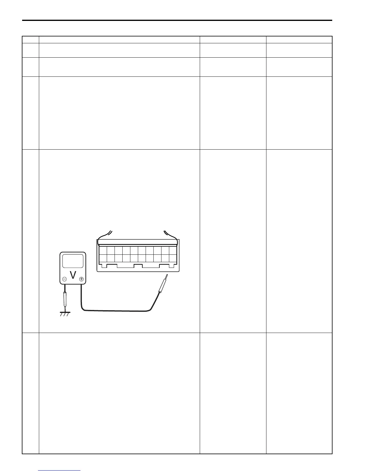
2) If connections are OK, check for voltage between “E53-
6” (“RED” wire) terminal and body ground with ignition
switch ON.
Is it approx. 5 V?
Go to Step 4. Go to Step 5.
4 Torque sensor 5 V reference power supply circuit check
1) With ignition switch turned OFF, connect torque sensor
connector.
2) Check for P/S control module connector (“E52”) for
proper connection.
3) Turn ignition switch ON.
4) Check for voltage between “Torque sensor 5 V reference
power supply circuit” terminal and body ground with
connector (“E52”) connected to the P/S control module.
Is it about 5 V?
Substitute a known-
good P/S control
module and recheck.
Replace steering gear
case.
5 Torque sensor 5 V reference power supply circuit check
1) With ignition switch turned OFF, disconnect P/S control
module connector.
2) Check that “Torque sensor 5 V reference power supply
circuit” is as following.
• Insulation resistance of “Torque sensor 5 V reference
power supply circuit” wire is infinity between its
terminal and other terminal at torque sensor
connector.
• Wiring resistance of “Torque sensor 5 V reference
power supply circuit” is less than 1 Ω.
• Insulation resistance of “Torque sensor 5 V reference
power supply circuit” between its circuit and vehicle
body ground is infinity.
Is circuit in good condition?
Replace P/S control
module.
Repair or replace
defective circuit.
20
E52
I4RS0A630013-02
 Loading...


