6C-24 Power Assisted Steering System:
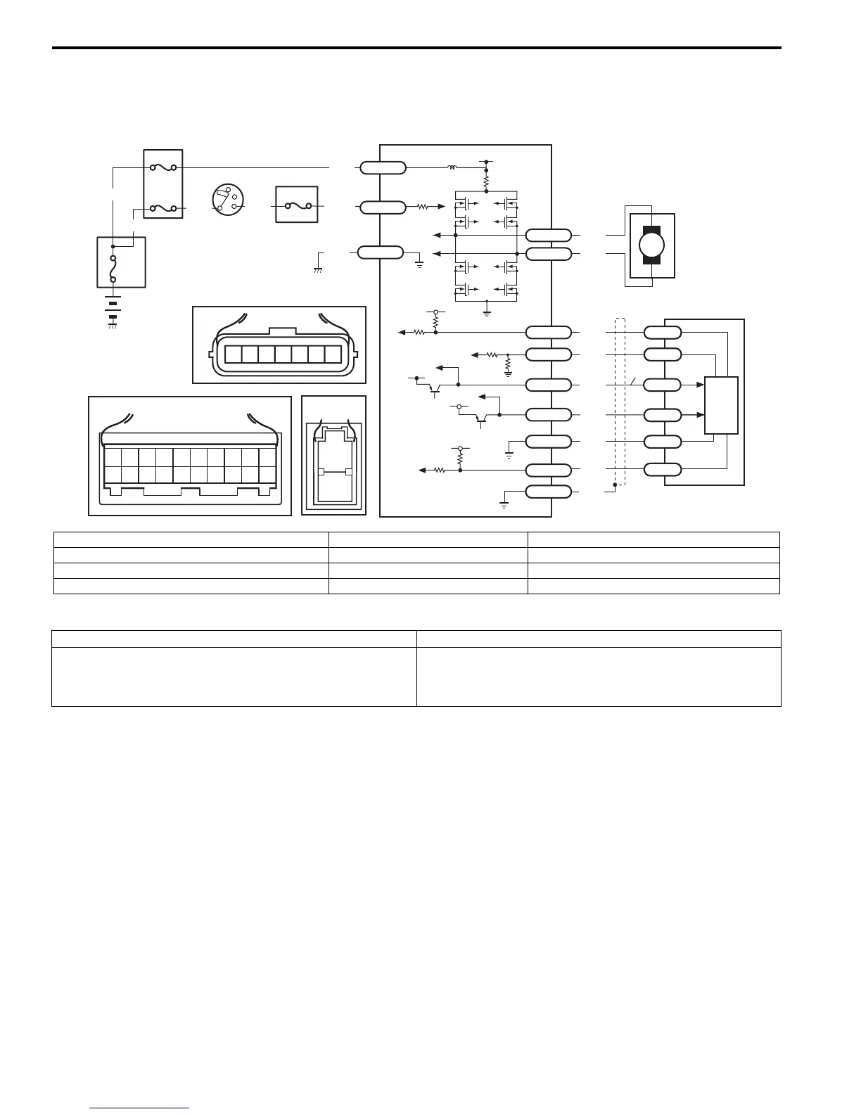
DTC C1119: Steering Torque Sensor Power Supply Circuit
S7RS0B6304016
Wiring Diagram
DTC Detecting Condition and Trouble Area
M
5V
BLK
RED
WHT
BLU
GRN
BRN
YEL
E51-1
E51-2
E52-18
E53-5
E53-7
E52-6
E52-8
E53-2
E52-9
E52-16
E52-19
GRY
5
6
7
12V
5V
5V
12V
RED
E52-20
E53-6
E53-4
E53-1
9
[A]
12
3
4
5
67
8
9
11
10
12 13
14
15
16
17 18 19
20
1
2
[B]
[C]
7654321
LT GRN
/BLK
E52-1
E49-1
GRN
GRN
WHT
BLK
WHY
8
3
4
4
4
4
1
2
E49-2
BLK
I7RS0B630008-01
[A]: Connector “E52” (viewed from harness side) 2. Ignition switch 6. Torque sensor
[B]: Connector “E49” (viewed from harness side) 3. Junction block assembly 7. Torque sensor amplifier
[C]: Connector “E53” (viewed from harness side) 4. Fuse 8. Individual circuit fuse box No.1
1. Main fuse box 5. P/S control module 9. Main power supply for torque sensor circuit
DTC detecting condition Trouble area
Circuit voltage of torque sensor main power supply is less
than 7.5 V for 1 second continuously
(1 driving cycle detection logic)
• Torque sensor circuit
• Torque sensor
• P/S control module
 Loading...


