6C-34 Power Assisted Steering System:
P/S Control Module Power Supply and Ground Circuit Check
S7RS0B6304022
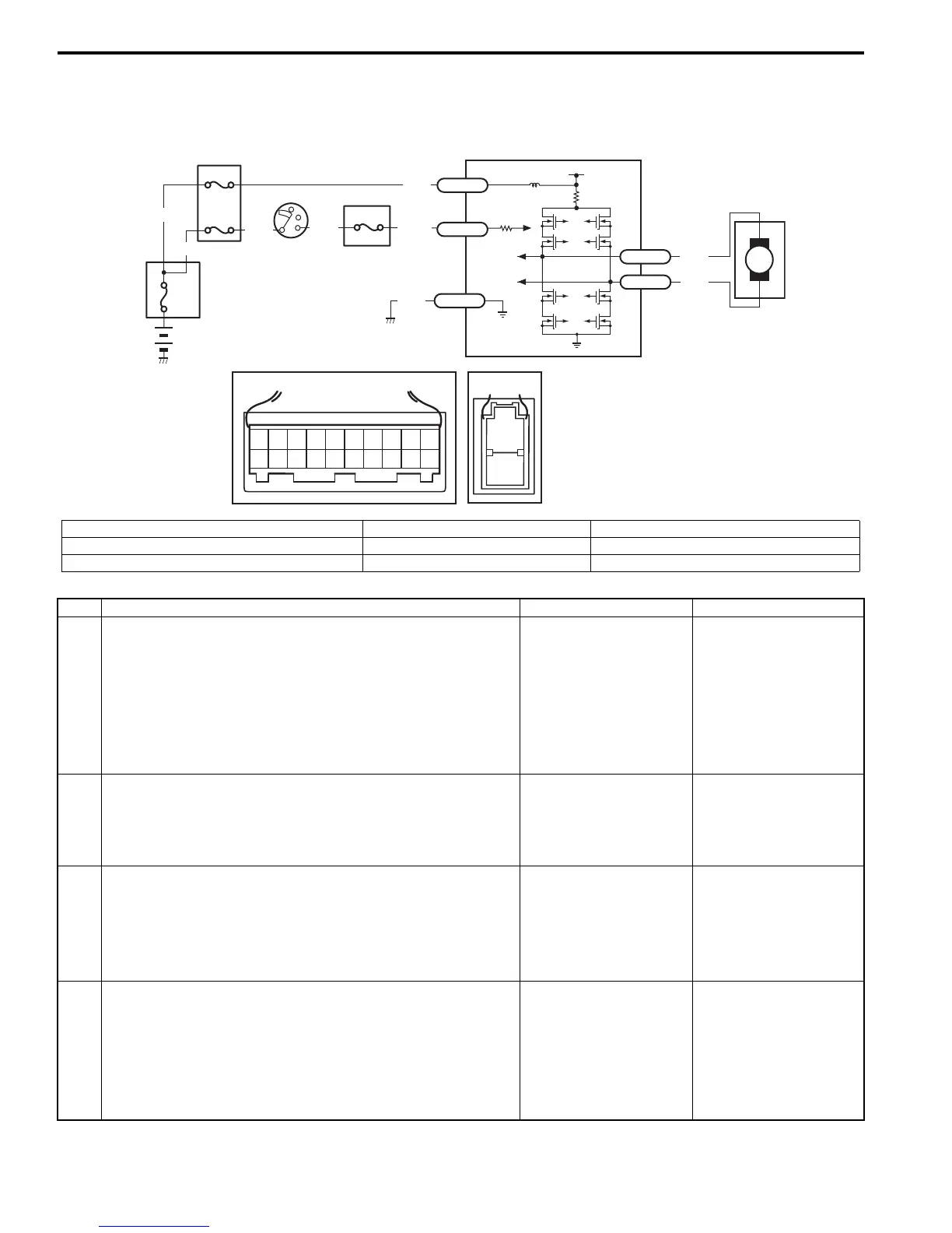
Wiring Diagram
1
[A]
12
3
4
5
67
8
9
11
10
12 13
14
15
16
17 18 19
20
[B]
7
1
2
M
BLK
RED
E51-1
E51-2
12V
LT GRN
/BLK
E52-1
E49-1
GRN
GRN
WHT
BLK
WHY
3
3
5
6
1
2
E49-2
BLK
I7RS0B630012-01
[A]: Connector “E52” (viewed from harness side) 2. Ignition switch 5. “EPS” fuse
[B]: Connector “E49” (viewed from harness side) 3. Individual circuit fuse box No.1 6. “IG1 SIG” fuse
1. Main fuse box 4. Junction block assembly 7. P/S control module
Step Action Yes No
1 Circuit fuse check
1) Disconnect P/S control module connector with ignition
switch turned OFF.
2) Check for proper connection to P/S control module
connector at “E49-1”, “E49-2” and “E52-1” terminals.
3) If OK, check “P/S” fuse and “IG1 SIG” fuse for blowing.
Are “P/S” fuse and “IG1 SIG” fuse in good condition?
Go to Step 2. Replace fuse(s) and
check for short in
circuits connected to
fuse(s).
2 Power supply circuit check
1) Measure voltage between “E49-1” terminal of P/S
control module connector and body ground.
Is voltage 10 - 14 V?
Go to Step 3. “GRN” or “BLK” wire is
open circuit.
3 Ignition signal check
1) Turn ignition switch to ON position.
2) Measure voltage between “E52-1” terminal of P/S
control module connector and body ground.
Is voltage 10 - 14 V?
Go to Step 4. “LT GRN/BLK” or “GRN”
wire is open circuit.
4 P/S control module ground circuit check
1) Turn ignition switch to OFF position.
2) Disconnect connectors from P/S control module.
3) Measure resistance between “E49-2” terminals of P/S
control module connector and body ground.
Is resistance 1
Ω
or less?
Go to Step 5. “BLK” wire is open or
high resistance circuit.
 Loading...


