Air Conditioning System: Manual Type 7B-11
5) Warm up engine to the normal operating
temperature and keep it at the specified idle speed.
6) Turn A/C switch ON, set blower speed selector at
maximum speed position, temperature selector at
maximum cold position, airflow selector at face
position, and air intake switch at recirculation
position. (Confirm that A/C compressor and
condenser fans are working.)
7) Wait for ten minutes to stabilize the A/C operation.
8) Open front windows, front doors and engine hood.
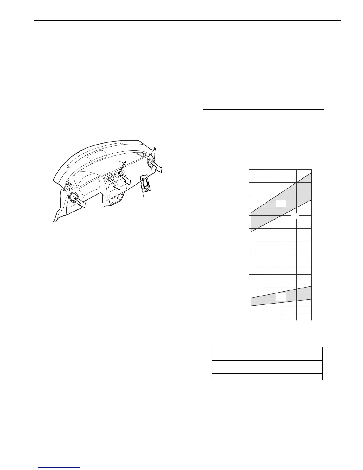
9) With about 20 mm (0.8 in.) of dry bulb thermometer
(1) put right in front of center ventilation louver and a
wet and dry bulb thermometer (2) near air inlet of
HVAC unit.
10) Check for each pressure of low side and high side if
it is within shaded range of graph. If each gauge
reading is out of specified pressure, correct defective
part referring to the following table.
NOTE
Pressure registered on gauge varies with
ambient temperature. Therefore, use the
graphs when determining if pressures are
normal or not.
Low side and high side pressure example,
Gauges should read as follows when ambient
temperature is 30 °C (86 °F)
Pressure on high pressure gauge (HI): 1590 –
1940 kPa (15.9 – 19.4 kg/cm
2
)
Pressure on low pressure gauge (LO): 270 – 430
kPa (2.7 – 4.3 kg/cm
2
)
2
1
I4RS0B720004-01
[A]: Pressure of high pressure gauge
[B]: Pressure of low pressure gauge
[C]: Ambient temperature
[D]: Humidity
[E]: Acceptable range
22312.9 2200
0
1
2
3
30
70
30
70
%
4
5
6
7
8
9
10
11
12
13
14
15
16
17
18
19
21298.7 2100
20
14.2
28.4
42.7
56.9
71.1
85.3
99.5
113.8
128.0
142.2
151.4
170.6
184.9
199.1
213.3
227.5
241.7
256.0
270.2
284.4
100
200
300
400
500
600
700
800
900
1000
1100
1200
1300
1400
1500
1600
1700
1800
1900
2000
25 30 35
77 86 95
psi kPa kg/cm
2
C
F
“A”
“B”
“C”
“D”
23
2300327.1
[A]
[B]
[C]
[D]
[E]
[E]
I7RS0A721006-01
 Loading...


