SVAN 948 USER MANUAL
4 - 33
In the case when the SLOPE + is selected, the measurement starts when the arising signal will
pass the level determined in the LEVEL. The measurement is stopped when the conditions set in the
MEASURE SETUP sub-list are fulfilled, after pressing the <START / STOP> push-button or after
receiving remotely the proper control code.
In the case when the SLOPE - is selected, the measurement starts when the falling down signal will
pass the level determined in the LEVEL.
Notice: In VLM mode only one available, so-called “triggering signal” is the signal coming
from the RMS detector of the first channel.
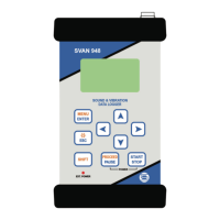
The view of the displays in the TRIGGER SETUP sub-list (path: MENU / INPUT / TRIGGER SETUP) with the
LEVEL modes selected
In the case when the LEVEL + is selected, in each second of the measurement the triggering
condition is checked; the measurement is registered only when the signal has the greater level then this
determined in the LEVEL and in the other case the measurement result is skipped.
In the case when the LEVEL - is selected, in each second of the measurement the triggering
condition is checked; the measurement is registered only when the signal has the lower level then this
determined in the LEVEL and in the other case the measurement result is skipped.
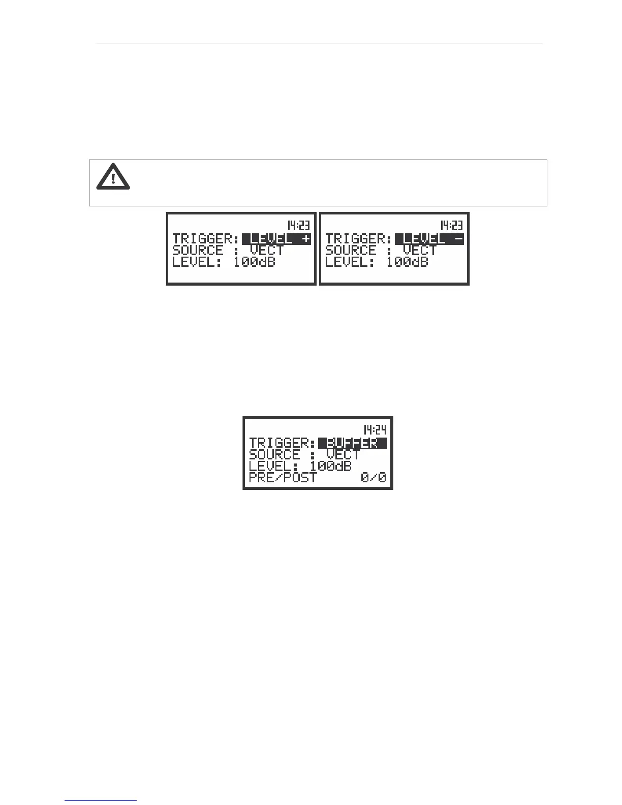
The view of the displays in the TRIGGER SETUP sub-list (path: MENU / INPUT / TRIGGER SETUP) with the
BUFFER mode selected
After the selection of the BUFFER mode the PRE/POST text appears on the display. This mode of
triggering influences the way the measurement results are registered in the buffer, namely: if the triggering
signal is greater then the selected LEVEL, the following results are saved in the buffer:
• registered directly before the fulfilment of the triggering condition; time of the registration can be
calculated by multiplying the value set in the PRE TRIGGER by the step taken from the
BUFFER STEP (the MEASURE SETUP sub-list);
• all measurement results up to the moment the triggering signal falls down the LEVEL;
• the results registered directly after the fulfilment of the triggering condition; time of the registration can
be calculated by multiplying the value set in the POST TRIGGER by the step taken from the
BUFFER STEP.
Selection of the triggering signal in SLM - SOURCE
It is assumed that in the sound level meter mode there are three triggering signal available: VECT,
VEC/SND, MAX.