SVAN 948 USER MANUAL .
2 - 4
2.2. INPUT AND OUTPUT SOCKETS OF THE INSTRUMENT
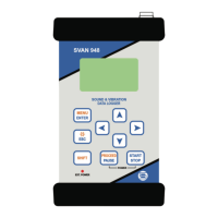
The measurement inputs, called Channels, are placed on the top cover of the instrument. There
are 4-pins Lemo compatible socket type ENB.0B.304 – Channels 1-3 and TNC – Channel 4, all with
IEPE power supply for the accelerometers or microphone preamplifiers. The microphone preamplifier
SV 12 has the proper plug-in with the screw for direct connection with the instrument but it is
recommended to use the preamplifier with any extension cable or gooseneck. The vibration transducer
attached to the unit has to have the same connector.
Notice: Pay attention that the TNC connector should be always twisted to the light resistance
but the Lemo connector is push-pull only.
The full description of the signals connected to the sockets is given in the Appendix C.
The view of the top cover of the SVAN 948 instrument in 1:1 scale
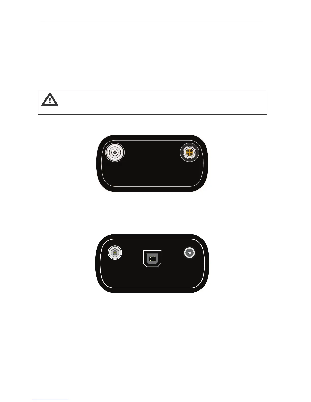
In the bottom cover three sockets exist: USB (in the figure below in the middle), AC / Int. (in the
figure below in the left side) and Ext. Power (in the figure below in the right side).
The view of the bottom cover of the SVAN 948 instrument in 1:1 scale
The USB 1.1 interface is the serial interface working with 12 MHz clock. Thanks to its speed this
interface is widely used in all PC. In the instrument the standard 4-pins socket is used described in details
in Appendix C.
The additional input / output socket, called AC / Int., is 1-pin LEMO compatible socket type
ERN.00.250 (the left one in the Fig. above). The function of this socket can be selected from menu (path:
MENU / SETUP / EXT. I/O SETUP / MODE). The socket can be used as: