16
www.teejet.com
MATRIX
®
Pro 570GS
•
MATRIX
®
Pro 840GS
HOME GUIDANCEFULL SCREEN IMPLEMENTINTRODUCTION GNSS RATE CONTROL APPENDIXSETUP
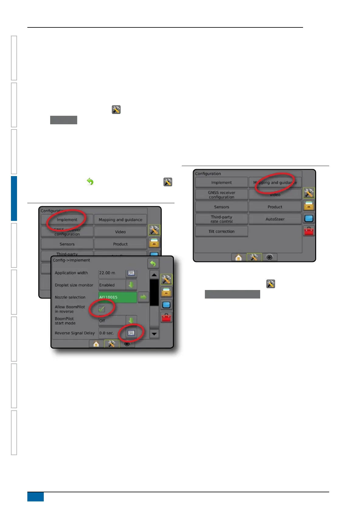
Reverse sense options
Reverse sense options are used when adding a Reverse
sense module or SCM Pro (Steering Control Module Pro for
FieldPilot Pro/UniPilot Pro) to any conguration.. This allows for
application mapping and control, and on-screen guidance when
traveling in reverse.
NOTE: For more information, see "Reverse Sense Module" in the
Implement chapter of this manual.
1. Press CONFIGURATION side tab .
2. Press Implement .
3. Select:
►Allow BoomPilot in Reverse [when available] – used to
enable BoomPilot function while traveling in reverse
►Reverse signal delay – used to set the delay when going
from forward to reverse or reverse to forward, after which
the vehicle icon on a navigation screen changes direction
4. Press RETURN arrow
or CONFIGURATION side tab
to return to the main Conguration screen.
Figure 4-10: Reverse sense options
Mapping and guidance [Lightbar]
Mapping and guidance options are used to congure the mapping
location, guidance width, cross track error shown on the lightbar.
An optional External Lightbar Module (ELM) may be used to
provide additional guidance information.
NOTE: In previous software versions, this feature was referred to
as "Lightbar".
● Mapping and guidance [console only] – used to congure
the mapping location, guidance width and guidance
sensitivity/cross track error shown on the on screen
guidance bar
● Mapping and guidance [using an external lightbar] – used to
congure an optional external lightbar module (ELM) which
provides additional guidance information.
Figure 4-11: Mapping and guidance
Mapping and guidance [console only]
1. Press CONFIGURATION side tab .
2. Press Mapping and guidance .
3. Select:
►Mapping location – establishes the layout of the location
from which the boundary or polygon will be mapped.
● Default location – While creating an external boundary or
polygon, the line will be to the exterior of the outermost
active section. While creating an interior boundary, the
line will be to the interior of the innermost active section.
If no sections are active, the boundary will be marked to
the end of the outermost section.
● User entry – in-line and lateral offset from the GNSS
antenna directions and distances can be specied by the
user. Up to ve (5) user entries can be created. See "
User Entered Mapping Location" for details.
►Guidance width – used to set the distance between
guidelines
►LED Brightness – used to adjust the brightness of the LEDs
►Display Mode – used to determine whether the lightbar
represents the swath or vehicle
● When set to "swath", the LEDs represent guideline
location and the moving LED represents the vehicle