43
98-05273-EN R7
MATRIX
®
Pro 570GS
•
MATRIX
®
Pro840GS
HOMESETUPGUIDANCE FULL SCREEN INTRODUCTIONGNSSRATE CONTROLAPPENDIX IMPLEMENT
Straight
The boom sections have no length and are on a line a xed
distance from the antenna.
Single section
No section control is available on the system.
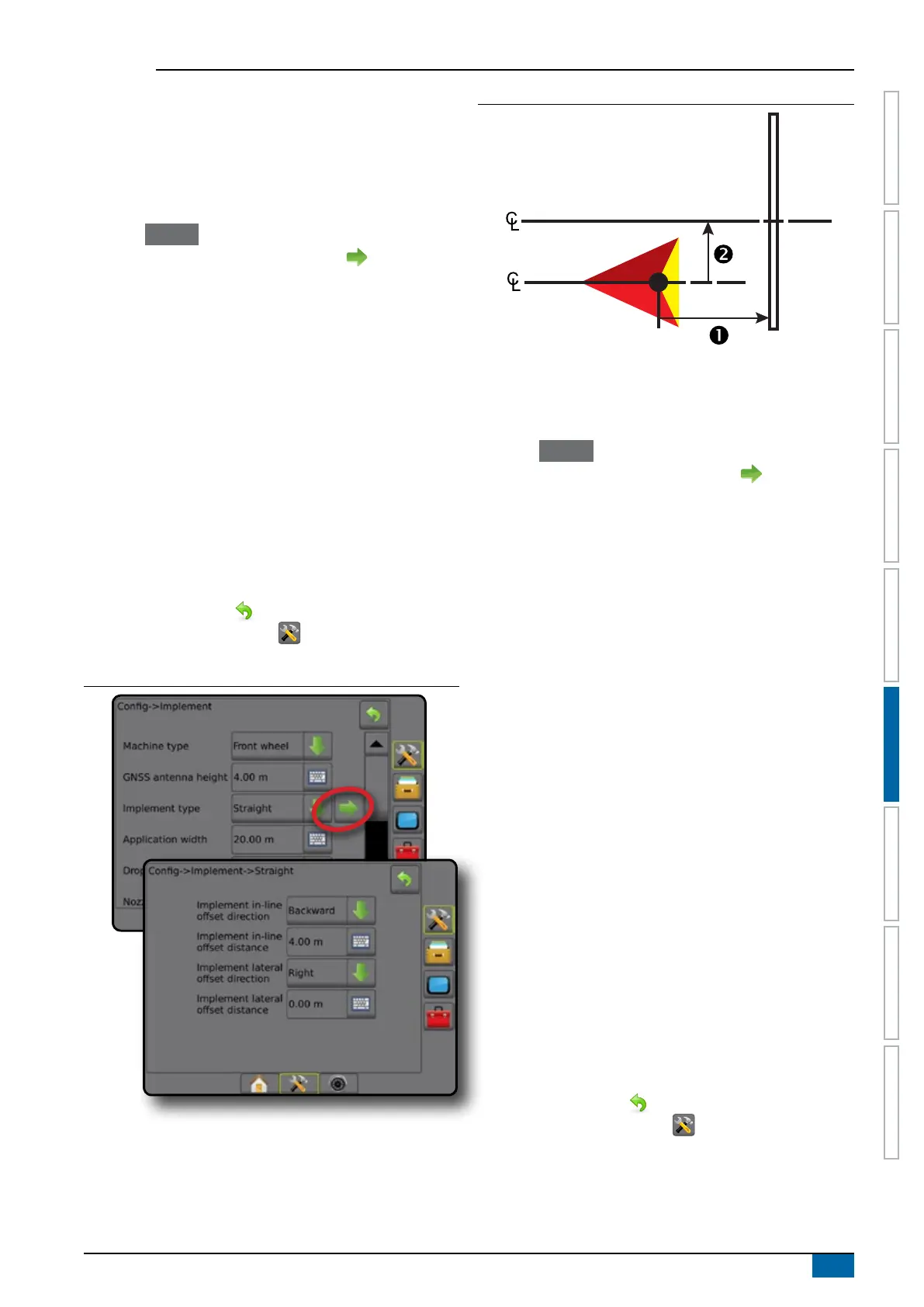
1. Select Straight implement type on Implement screen.
2. Press Implement Type NEXT PAGE arrow
.
3. Select from:
►Implement in-line offset direction
– establishes if
the implement is located in front of (forward) or behind
(backward) the GNSS antenna while facing in the vehicle's
forward direction
►Implement in-line offset distance – measured in parallel
to the centerline of the vehicle, denes the in-line distance
from the GNSS antenna to the implement in decimal meters
►Implement lateral offset direction – denes the lateral
direction, either left or right, from the centerline of the
machine to the center of the implement while facing in the
machine's forward direction
►Implement lateral offset distance – denes the lateral
distance from the centerline of the machine to the center of
the implement in decimal meters
4. Press RETURN arrow to return to the Implement screen
or CONFIGURATION side tab to return to the main
Conguration screen.
Figure 6-4: Single section
Figure 6-5: Offset Directions and Distances
Multiple sections
Section control is available (SmartCable, Section driver module
(SDM), or Switch function module (SFM).
1. Select Straight implement type on Implement screen.
2. Press Implement Type NEXT PAGE arrow .
3. Select from:
►Implement in-line offset direction – establishes if
the implement is located in front of (forward) or behind
(backward) the GNSS antenna while facing in the vehicle's
forward direction
►Implement in-line offset distance – measured in parallel
to the centerline of the vehicle, denes the in-line distance
from the GNSS antenna to the implement in decimal meters
►Implement lateral offset direction – denes the lateral
direction, either left or right, from the centerline of the
machine to the center of the implement while facing in the
machine's forward direction
►Implement lateral offset distance – denes the lateral
distance from the centerline of the machine to the center of
the implement in decimal meters
►Overlap – used to dene the amount of overlap allowed
when using automatic boom section control
►Delay on time – used to set the time when the section will
switch on when entering an area that has not been applied
NOTE: If the application turns on too soon when entering
an unapplied area, decrease the Delay on time. If the
application turns on too late, increase the Delay on time.
►Delay off time – used to set the time when the section will
switch off when entering an area that has been applied
NOTE: If the application turns off too soon when entering
an unapplied area, decrease the Delay off time. If the
application turns off too late, increase the Delay off time.
4. Press RETURN arrow to return to the Implement screen
or CONFIGURATION side tab to return to the main
Conguration screen.