17
98-05273-EN R7
MATRIX
®
Pro 570GS
•
MATRIX
®
Pro840GS
HOMEGUIDANCE FULL SCREENIMPLEMENT INTRODUCTIONGNSSRATE CONTROLAPPENDIX SETUP
● When set to "vehicle", the centre LED represents vehicle
location and the moving LED represents the guideline
►LED Spacing – used to set the distance away from the
guideline or vehicle each illuminated LED represents
4. Press RETURN arrow or CONFIGURATION side tab
to return to the main Conguration screen.
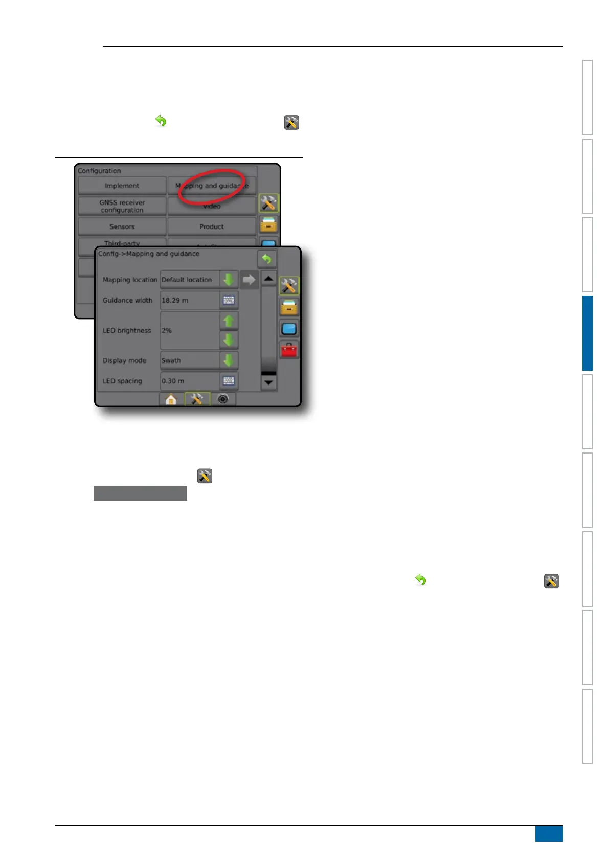
Figure 4-12: Mapping and guidance
Mapping and guidance using an external lightbar
Additional conguration options are available when using an
external lightbar.
1. Press CONFIGURATION side tab .
2. Press Mapping and guidance .
3. Select from:
►Mapping location – establishes the layout of the location
from which the boundary or polygon will be mapped.
● Default location – While creating an external boundary or
polygon, the line will be to the exterior of the outermost
active section. While creating an interior boundary, the
line will be to the interior of the innermost active section.
If no sections are active, the boundary will be marked to
the end of the outermost section.
● User entry – in-line and lateral offset from the GNSS
antenna directions and distances can be specied by the
user. Up to ve (5) user entries can be created. See "
User Entered Mapping Location" for details.
►Guidance width – used to set the distance between
guidelines
►LED Brightness – used to adjust the brightness of the LEDs
on the console
►Display mode – when External lightbar is "enabled",
determines whether the lightbars represent the swath or
vehicle
● When set to "swath", the LEDs represent guideline
location and the moving LED represents the vehicle
● When set to "vehicle", the centre LED represents vehicle
location and the moving LED represents the guideline
►LED Spacing –
● When External lightbar is "enabled", sets the distance
away from the guideline or vehicle each illuminated LED
represents
● When External lightbar is "disabled", sets the distance
around the guideline that is perceived as zero error
►External lightbar – enable/disable use of the external
lightbar
4. With the External Lightbar Module (ELM) enabled, select from:
►External Lightbar LED Brightness – adjusts the brightness
of the external lightbar LEDs
►External Lightbar Text Brightness – adjusts the brightness
of the external lightbar text
►External Cross Track – enable/disable display of cross track
error information on the external lightbar
►External Swath Number – enable/disable display of swath
number information on the external lightbar
►External Speed – enable/disable display of speed
information on the external lightbar
►External Actual Rate [available with Third-party Rate
Control] – enable/disable display of actual rate information
on the external lightbar
►External Target Rate [available with Third-party Rate
Control] – enable/disable display of target rate information
on the external lightbar.
►External Applied Product [available with Third-party Rate
Control] – enable/disable display of applied product
information on the external lightbar
5. Press RETURN arrow
or CONFIGURATION side tab
to return to the main Conguration screen.