Key lock (locks the front panel keyboard, including
the touch screen)
External Trigger: pulsewidth≥1μS
10.1.1.3 Signal Line Description
The Handler interface has 3 signal: comparison output, control output and control input. The
following are the signal definitions of the HANDLER interface when the bin comparison function is
used.
Compare output signal: /BIN1 - /BIN10, PASS, FAIL.
Control output signal: /INDEX (analog measurement end signal)
/EOM (measurement end and comparison data valid signal)
/ALARM (instrument power down signal).
Control input signal: /EXT.TRIG (external trigger signal)
/Keylock.
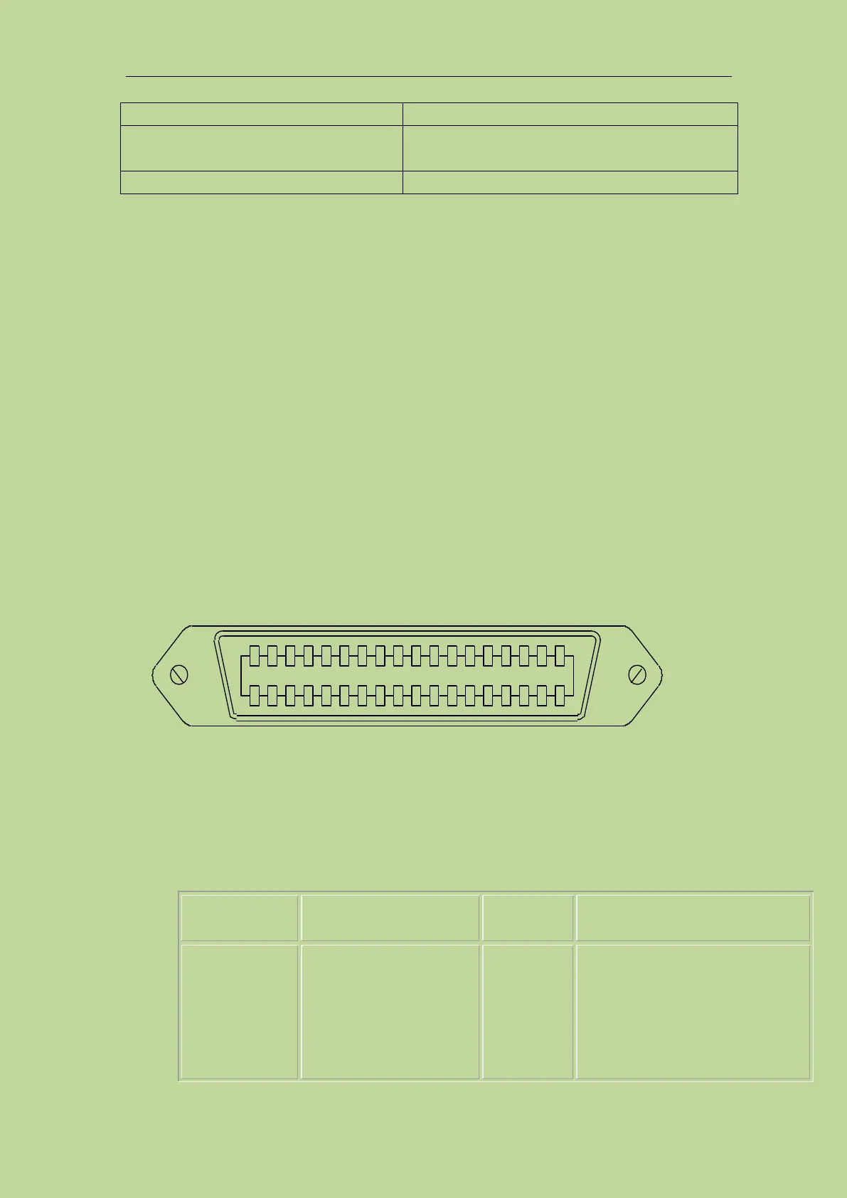
The interface diagram of the above pins is shown in Figure 10-1.
See Table 10-3 for the signal assignment and brief description of the above pins.
The timing diagram is shown in Figure 10-3.
Note: Figure 10-1 is just the interface definition of the bin sorting, and the definition of
the list sweep sorting and the transformer single test sorting are different.
Table 10-3 Signal distribution table for the pins comparison function:
/BIN1
/BIN2
/BIN3
/BIN4
/BIN5
/BIN6
BIN sorted result
All/BIN(BIN number) output are all
open collector output.
1
2
3
4
5
6
7
8
9
10
11
12
13
14
15
16
17
18
19
20
21
22
23
24
25
26
27
28
29
30
31
32
33
34
35
36
/BIN 1
/BIN 2
/BIN 3
/BIN 4
/BIN 5
/BIN 6
/BIN 7
/BIN 8
/BIN 9
/OUT
/AUX
/EXT TRIG
EXT.DCV2
+5V COM1
COM2
/PHI
/PLO
/SREJ
N.C
/KEY LOCK
N.C
EXT.DCV1
/ALARM
/INDEX
/EOM
COM1
COM1
COM2
EXT.DCV1
N.C
N.C
+5V
+5V
/EXT TRIG
EXT.DCV2
Figure 10-1 HANDLER connection interface pin definition