54321
HANDLER
SCANNER
CYLINDER
TEST LINE
FOOT.C
+ -
N1N9VCC
GO NG S R GND
11) Fixture pin number. In above figure, 1~20/24 is the corresponding pin number.
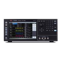
7.4 Rear panel of scanning box
Introduction to each number on the lower panel
1. TEST LINE: inlet port of the test cable, TH1901L 6-terminal test box is connected to inner part
of TH1901A/B through this line.
2. CYLINDER: 24V DC voltage output terminal, providing the working voltage for TH1901A
solenoid valve.
3. FOOT. C: Used to connect footswitch.
4. SCANNER: Signal control port. Use TH26016 control line to connect the scanning box with
TH2840X through SCANNER port.
5. HANDLER: HANDLER port. Refer to section 7.5 for instruction of HANDLER port.
NOTE: There is a hole in the left panel of TH1901A/B, the inner adjustable potentiometer can be
sued to adjust the volume of beep.
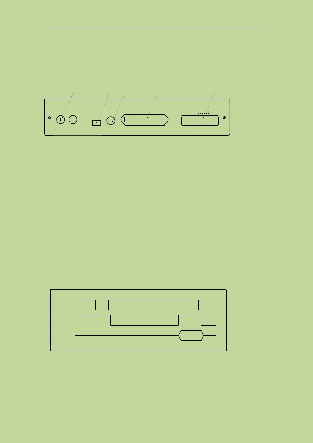
7.5 HANDLER interface
7.5.1 Timing diagram of HANDLER signal
7.5.2 Distribution and connection diagram for HANDLER
The distribution and external circuit of HANDLER signal pin: