delay 1 measurement 2comparison 3display
time time time time
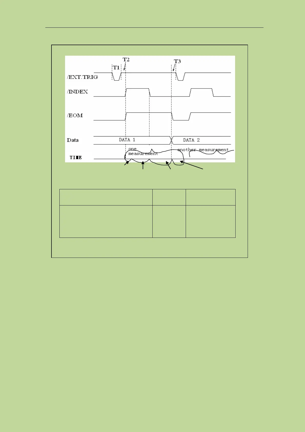
T1: trigger pulse-width
T2:delay time
T3:the trigger waiting time after /EOM
output
---
Display time
3
+
200us
---
1. for the measurement time, please refer to 8.1.9;
2. the typical comparison time is approximately 0.1ms;
Figure 10-3 the timing chart
10.1.2 Electrical feature
As it is shown above, the signal definition for the comparison and the list sweep comparison are
different. But the electrical feature is same. So the description can be applied to BIN comparison
and list sweep comparison.
10.1.2.1 DC isolation output signal
Each DC output (pin 1 to 11, 19 to 24, and 29 to 31) is isolated via an open collector optocoupler
output. The output voltage of each line is set by a pull-up resistor on the HANDLER interface board.
The pull-up resistor is connected with the internal supply voltage (+5V) or with the external supply
voltage (EXTV: +5V-24V) by jumper.
The DC isolated output signal utilizes a dedicated electrical system which is independent of the