The measurement switch of each parameter is selected to be ON, and the upper and lower limits are
set at the same time, then the parameter participates in the sorting. Note that this parameter does not
participate in sorting without setting upper and lower limits.
10.4 Transformer scan HANDLER description
In Transformer scan, HANDLER uses two DR-25P sockets, namely Trans Handler and Trans
Controller. It can provide up to 30 independent sorting signals NS1-NS30, in addition to PASS, NG,
TEST and other signals.
10.4.1 Technical Description
10.4.1.1 Output Signal
Active low, open collector, optoelectronic isolation, ULN2003 Drive Enhancement
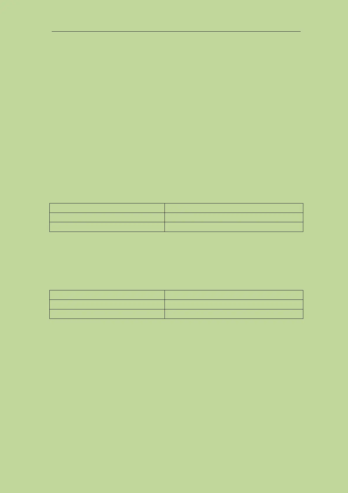
Table 10-11 Output Signal
“All measurement end” signal
10.4.1.2 Input Signal
Active low, optoelectronic isolation
Table 10-12 Input Signal
10.4.1.3 Signal Line Definition
The HANDLER interface of transformer scan uses three signals: compare output, control input, and
control output. The following are the signal definitions of the HANDLER interface when using the
transformer scan function.
Compare output signals: NS1–NS30, PASS, FAIL.
Control output signal: TEST (analog measurement completion signal)
Control input signal: EXT_START (external trigger signal)
EXT_RESET (reset signal).
See Table 10-13 (Trans Handler) and Table 10-14 (Trans Controller) for the signal assignment and
brief description of the above pins.