control output signal. Therefore, the processor board has a common line for two separate circuits:
COM1 and COM2.
The electrical characteristics of the DC isolated output are divided into two types, see Table 10-4.
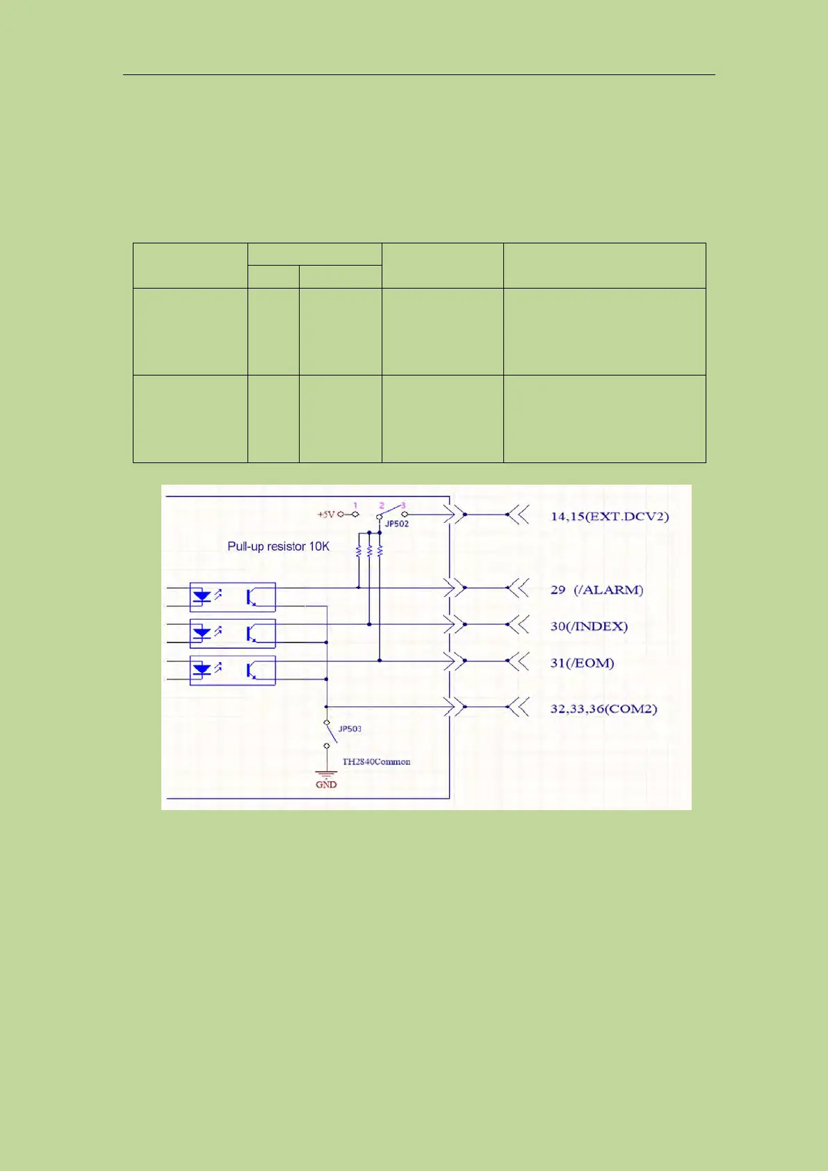
The output circuit configuration of the test result output signal is shown in Figure 10-5, and the
output circuit configuration of the control output signal is shown in Figure 10-4.
Table 4 the electrical feature of the DC isolation output
Figure 10-4 Control signal output circuit
Reference ground for the circuit
Compared signal
/BIN1 - /BIN10
/PASS
/FAIL
Internal pull-up voltage:
TH2840 GND
EXTV1:
COM1
Control signal
/INDEX
/EOM
/ALARM
Internal pull-up voltage :
TH2840 GND
EXTV2 :
COM2