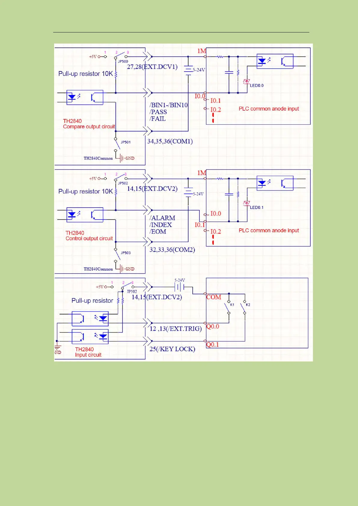
Figure 10-7 PLC wiring diagram where handler interface and input circuit are common anode
Figure 10-7 Description: EXT.DCV1 and EXT.DCV2 can use the same set of external power
supplies, or they can use different sets of power supplies. The corresponding low end of EXT.DCV1
is COM1, and the corresponding low end of EXT.DCV2 is COM2. The input circuit and the control
output circuit use the same group of power supplies, namely EXT.DCV2. The wiring method
provided in this figure is a typical connection method, and it needs to be flexibly applied according
to the actual situation in practical application.