"Analog measurement end" signal
"End of all measurements" signal
Provides an alert when a momentary power failure
or processor interface board reset is detected.
10.2.2.2 List Sweep Input Signal
The input signal is the same as for bin sorting, see section 10.1.1.2.
10.2.2.3 Signal Line Definition
The list sweep sorting HANDLER interface uses three signals: compare output, control input and
control output. The following are the signal definitions of the HANDLER interface when the list
sweep sorting function is used.
The signal definition of the list sweep comparison function is different from that of the BIN
comparison function. Its definition is as follows:
Compare output signals: /FAIL1 - /FAIL10, PASS, FAIL.
The /FAIL1 - /FAIL10 signal indicates the pass or out-of-tolerance judgment of each sweep point,
see Figure 10-9. The /PASS and /FAIL signals are indicated as total judgment signals. These signals
will be output when a sweep measurement is completed.
Control output signal: /INDEX (analog measurement completion signal)
/EOM (measurement end and comparison data valid signal)
/ALARM (instrument power down signal).
SEQ sweep mode: The /INDEX signal is asserted valid when the analog measurement of the last
sweep point is completed. The /EOM signal is asserted valid after each step of measurement and
comparison is completed. The timing diagram is shown in Figure 10-10.
STEP sweep mode: The /INDEX signal is asserted valid after the analog measurement of each
sweep point is completed. The /EOM signal is asserted valid after each step of measurement and
comparison is completed. The timing diagram is shown in Figure 10-10.
Control input signal: /EXT.TRIG (external trigger signal)
The interface diagram of the above pins is shown in Figure 10-1.
See Table 10-6 for the signal assignment and brief description of the above pins.
The timing diagram is shown in Figure 10-10.
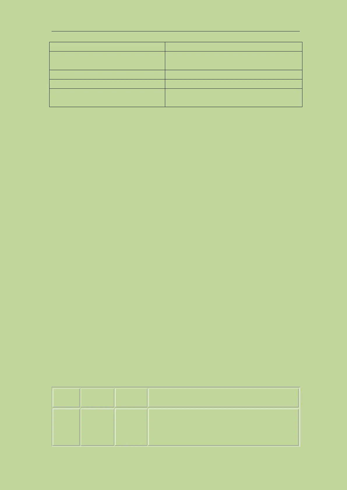
Table 10-6 Pin distribution table of List sweep sorting function
/FAIL1
/FAIL2
/FAIL3
/FAIL4
Out of the limit of sweep point1
Out of the limit of sweep point2
Out of the limit of sweep point3
Out of the limit of sweep point4