Troubleshooting in theField 7
When GNSS is working correctly in a dual-GNSS system, you will see the
following activity:
l The left GNSS receiver’s LEDs will behave as described above in the single-
GNSS system.
l The right GNSS receiver’s power LED will be on solid.
l The right GNSS receiver’s data link LED will be on solid.
l The right GNSS receiver’s satellite LED will flash slowly.
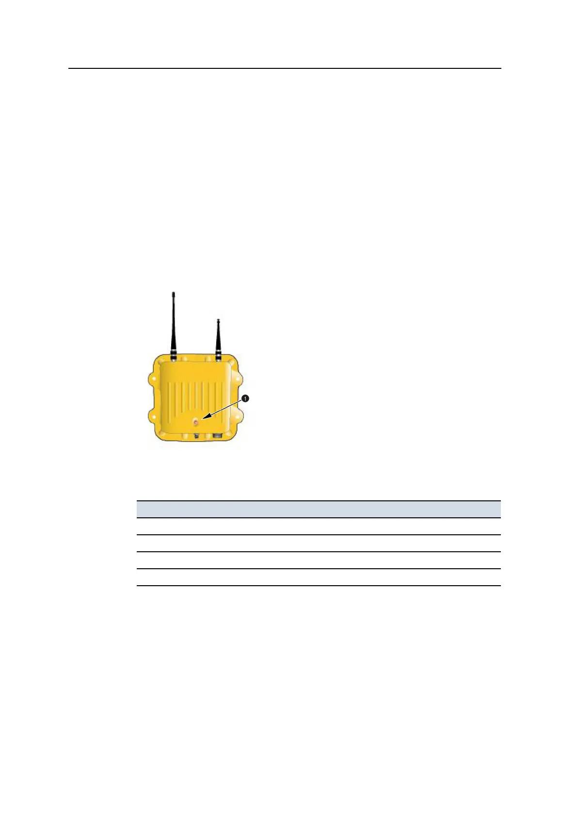
7.6.3 SNRxxx radio modem status indicator
The housing for the SNRxxx radio modems are fitted with an LED data/power
indicator light (1).
The LED can flash in a number of different patterns depending on the situation, as
shown below:
LED pattern Status
Off No power to radio.
On solid Power is available, but the radio is not synchronized with the base station.
Irregular flashing Power is available, the radio is synchronized, but the radio is losing data.
Steady flashing at 1Hz Power is available, the radio is synchronized, and receiving data.
GCS900 Grade Control System for Excavators Operator's Manual 181