Using 3D Guidance in the Field 5
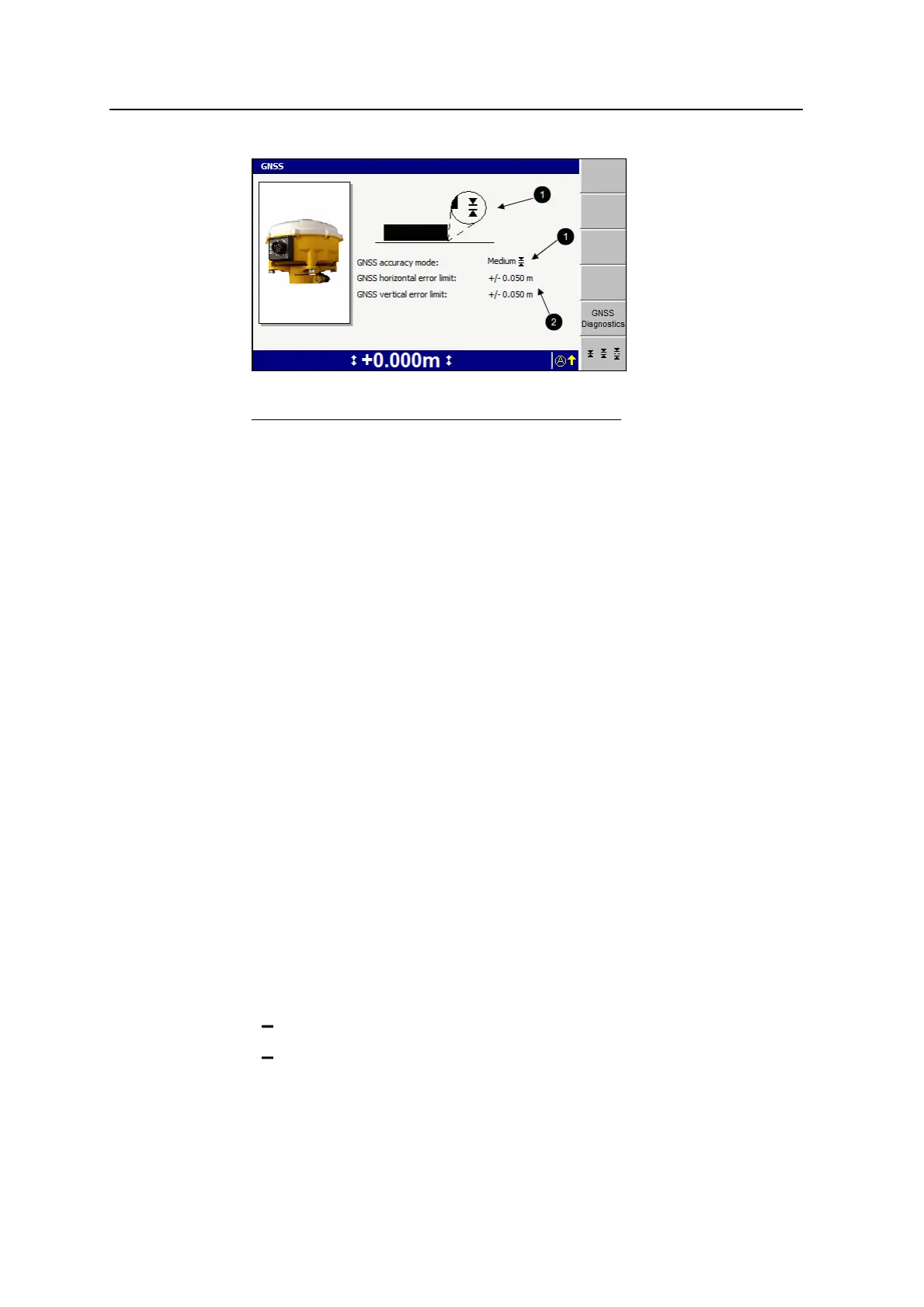
1
Current accuracy setting
2
Error limits
Figure 5.1 GNSS accuracy mode dialog
3.
To swap between fine, medium, and coarse accuracy modes, press B.
Note – When coarse mode is selected, your site supervisor can enable the use
of low accuracy corrections broadcast from satellites (SBAS). If you use SBAS
GNSS, check with your site supervisor that you have a suitable GNSS
configuration file loaded into the GNSS receiver(s).
4. To view left and right receiver, data link, and Sky Plot diagnostics, press GNSS
Diagnostics to open the GNSS diagnostics dialog.
5.
To confirm the settings, press \; to exit without saving changes, press =.
5.2.6 GNSS geoid grid support
A small embedded geoid grid can be placed in a GNSS receiver configuration file.
The geoid grid is used to determine the GNSS receiver elevation.
This gives you more accurate elevations, especially in highly mountainous areas
where the geoid cannot be easily approximated with an inclined plane adjustment.
To load a geoid grid into the GNSS receiver configuration file, see your site
supervisor.
When the GNSS position is out of the range of the loaded geoid grid, the following
flashing message appears on the guidance screen.
Out of Geoid Range
When this flashing message appears:
l The positions that the GNSS receiver generates are flagged as:
not having a valid GNSS coordinate system
out of range from the geoid
GCS900 Grade Control System for Excavators Operator's Manual 113