3 Preparing to Work
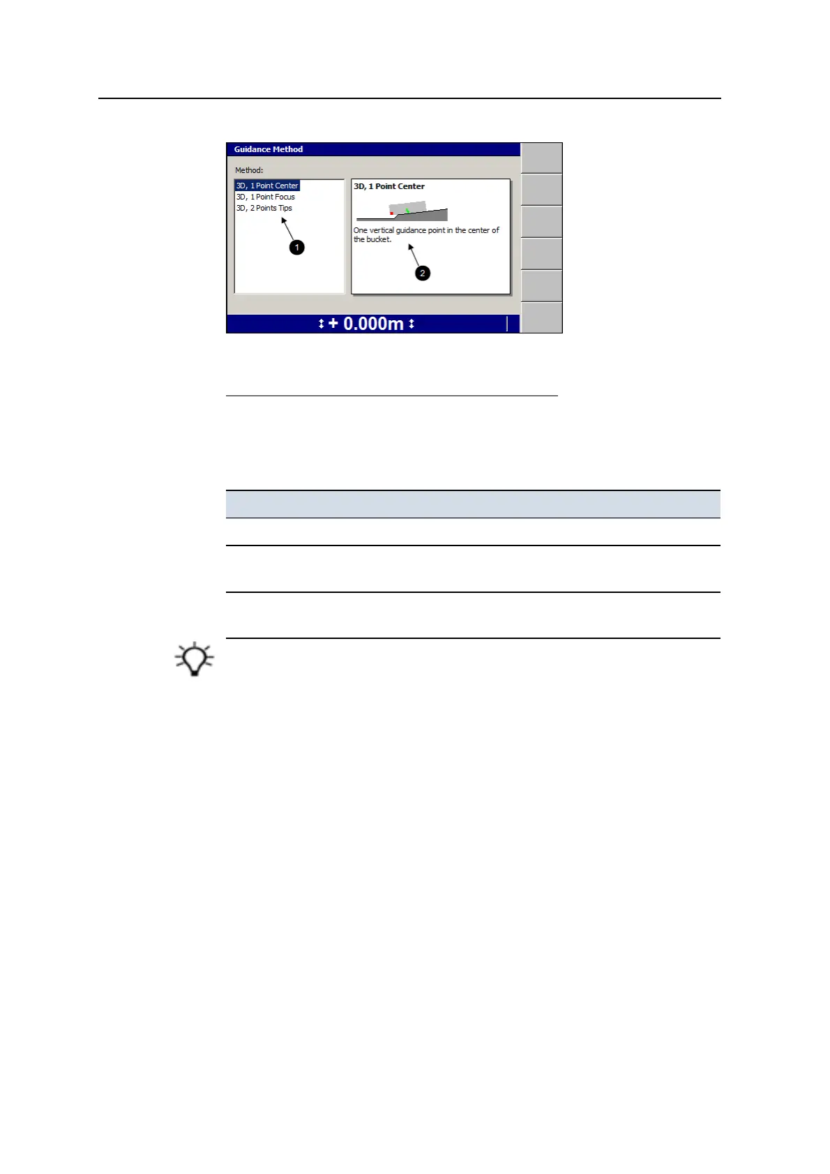
1
List of available vertical
guidance methods
2
Brief description of
highlighted vertical
guidance method
Figure 3.1 Example of a 3D Guidance Method dialog
4. Highlight the vertical guidance method you want to use.
To use in the field, see Chapter 5, Using 3D Guidance in the Field.
Method Description
3D, 1 Point Center One vertical guidance point in the center of the bucket.
3D, 1 Point Focus One vertical guidance point inset 200 mm (8 inches) from the
bucket focus.
3D, 2 Points Tips Two vertical guidance points, inset 200 mm (8 inches) from the
bucket tips.
Tip – Use the default 3D, 1 Point Center method, unless you have a good reason to use
another vertical guidance method.
5.
To confirm the settings, press \; to exit without saving the changes, press
=.
3.12 Selecting a 2D guidance method
This is covered in Chapter 4, Using 2D Guidance in the Field.
To select a guidance method, see4.4 Selecting or creating a guidance model.
76 GCS900 Grade Control System for Excavators Operator's Manual