Technical Description TITANUS MICRO·SENS
®
2 – 4 Data: 01/09 MS_A_02-a-en-e
steps of 0.1 %/m. The alarm is shown on the device via the alarm display
and forwarded to a connected fire alarm system (FAS).
By changing the delay time with the diagnosis tool, the forwarding of
alarms and faults can be set.
The intelligent LOGIC·SENS signal processing device serves to blank out
fire-like false alarms and ensures high false alarm safety.
Airflow monitoring An airflow sensor checks the connected pipe system for breaks and
blockages.
Depending on the design of the pipe system and the setting on the air-
flow sensor, the blockage of just one aspiration aperture can be picked
up. The airflow monitoring is temperature-compensated and can be
made air pressure-dependent.
At the end of the adjustable delay time, the fault is shown on the smoke
detection system and a corresponding message is forwarded to the
central fire alarm point via a contact. The monitoring windows can be
adjusted to the environmental conditions.
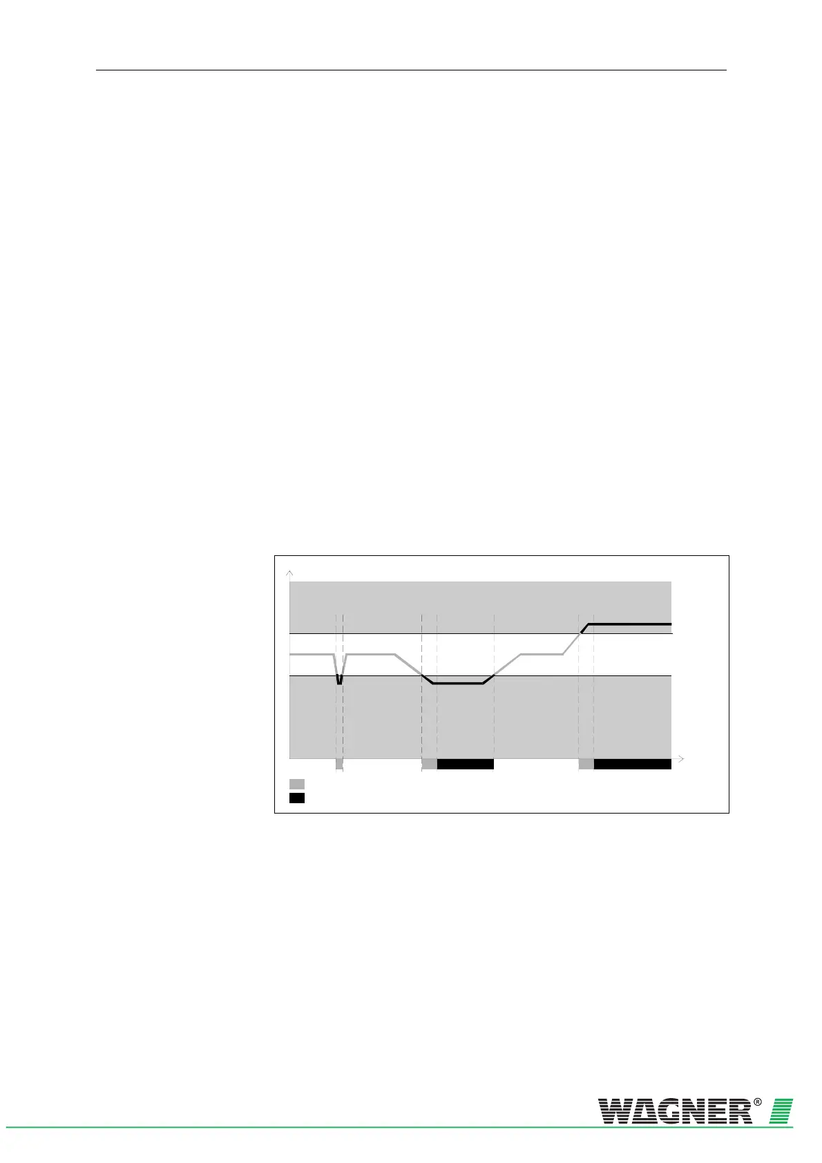
The principle of the airflow sensor signalling process can be seen in
0HFig.
2.6 .
Device monitoring The detection unit is monitored for dirt and signal fault. Any fault which
occurs is displayed at the TITANUS MICRO·SENS
®
and can be for-
warded to the FAS via a contact.
Signal from the air flow sensor
Mo nitoring
window
Time
Blockage
Break
Airflow too high
Delay time
Fault message
Airflow normal
Airflow
too low
Fig. 2.6: Example signal pattern in the airflow sensor during faults
Airflow adjustment Airflow adjustment on the TITANUS MICRO·SENS
®
is fully automatic
when the detection unit is inserted in the device base, if previously the
Jumper X4 had been changed. This plug & play reduces the time needed
for commissioning to a minimum. It is also possible, however, to adjust
the airflow using the DIAG 3 diagnosis tool. This means the initialisation
phase can be carried out in an air pressure-dependent or air pressure-
independent manner.
 Loading...


