Technical Description TITANUS MICRO·SENS
®
2 – 8 Data: 01/09 MS_A_02-a-en-e
TITANUS MICRO·SENS
®
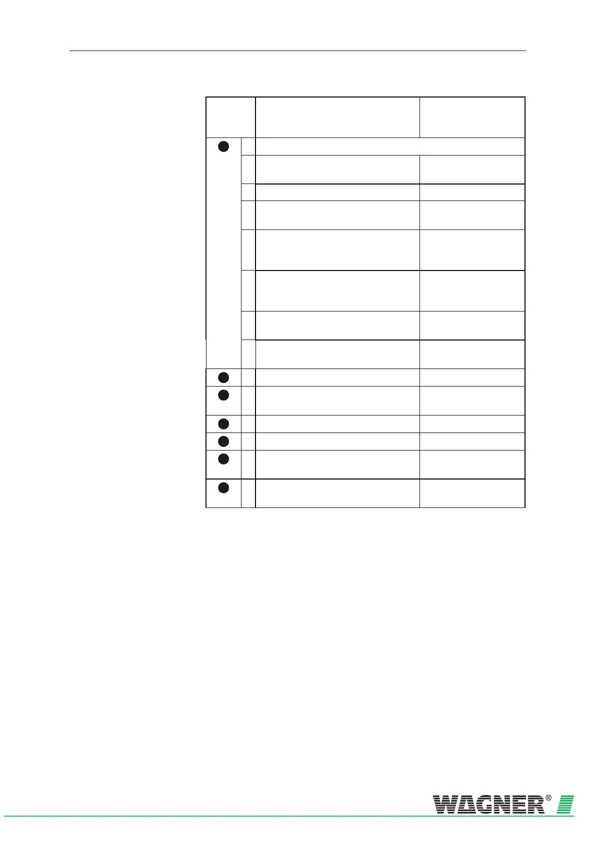
Number
in 2HFig.
2.8
Function Explanation
1
Displays (see to Fig. 2.8
3HFig. 2.9)
* Smoke level display 1 to 10
(10 yellow LEDs)
Current smoke level
Operation (green LED) Operation display
Fire alarm (red LED) Smoke level (where main
alarm threshold is set)
Action alarm (red LED) Smoke level (Value as
per main alarm threshold
10 – 80 % adjustable)
Fault (yellow LED) Pipe system fault or
ventilator breakdown or
detector module fault
* Locating the seat of the fire A – E
(5 red LEDs)
Locating the seat of fire
Infrared interface Commissioning and fault
diagnosis
2
Air sampling pipe connection for ∅ 25 mm pipe system
3
Cable feed, fire alarm cable for switching
on FAS and/or power supply (in / out)
2 x M 25
4
Air return pipe connection for air return
5
Cable feed fire alarm cable 8 x M 20
6
Cable entries (small) 2 x M 20 for cable with
∅ of 1 to 13 mm
7
Cable entries (large) 1 x M 25 for cable with
∅ of 1 to 18 mm
* optional
 Loading...


