E
HOW TO USE THIS MANUAL
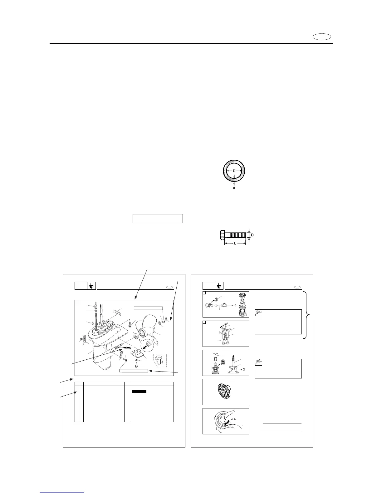
1 To help identify parts and clarify procedure steps, there are exploded diagrams at the
start of each removal and disassembly section.
2 Numbers are given in the order of the jobs in the exploded diagram. A circled number
indicates a disassembly step.
3 Symbols indicate parts to be lubricated or replaced (see “SYMBOLS”).
4 A job instruction chart accompanines the exploded daiagram, providing the order of
jobs, names of parts, notes in jobs, etc.
Example:
O-ring size 39.5 x 2.5 mm: inside diameter (D) x ring diameter (d)
5 Dimension figures and the number of parts are provided for fasteners that require a tight-
ening torque:
Example:
Bolt or screw size 10 x 25 mm (2) : M10(D) x 25 mm (L)
6 Jobs requiring more information (such as special tools and technical data) are described
sequentially.
17 Nm (1.7 m•kg, 12 ft•lb)
5 Nm (0.5 m•kg, 3.6 ft•lb)
1
2
3
4
5
8
9
12
17
16
15
13
14
10
14
11
6
7
18
2. Remove:
9 Oil seals
9 Needle bearing
Propeller shaft housing ass’y disassembly
1. Remove:
9 Reverse gear
9 reverse gear shim (s)
9 Ball bearing 1
A For USA and CANADA
B Except for USA and CANADA
E
PROPELLER SHAFT HOUSING ASS’Y
LOWR
6-10
Slide hammer set 2:
YB-06096
Stopper guide plate 3:
90890-06501
Bearing puller 4:
90890-06535
Stopper guide stand 5:
90890-06538
Slide hammer set 1:
YB-06096
Driver rod 2:
YB-06071/90890-06604
Needle bearing attachment 3:
YB-06081/90890-06616
SERVICE POINTS
Gears inspection
1. Inspect:
9 Tooth
9 Dog
Wear/Damage → Replace.
Bearings inspection
1. Inspect:
9 Bearing
Pitting/Rumbling → Replace.
NOTE:
Turn the bearing by fingers and check the
bearing pitching
A
B