5-10
REMOVAL AND INSTALLATION CHART
Step
1
2
3
4
5
6
7
8
9
10
Q’ty
3
1
2
1
1
1
1
1
1
1
Service points
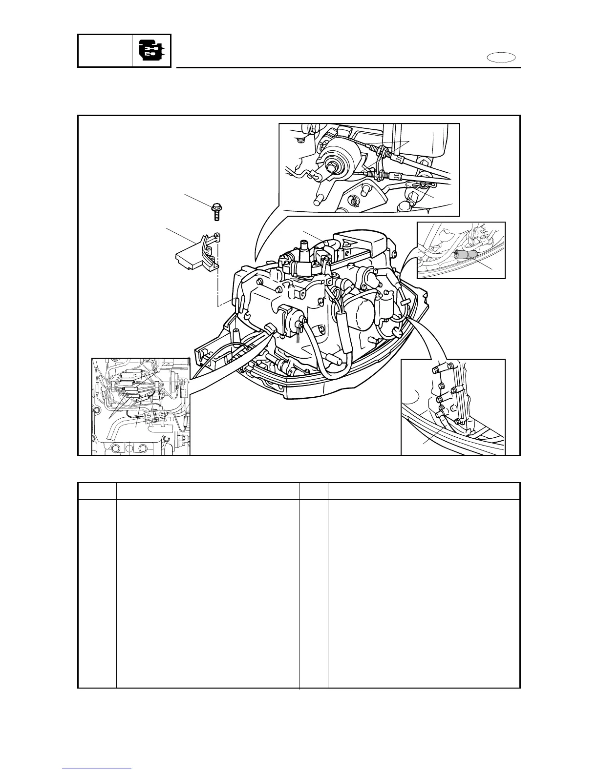
Follow the left ”Step” for removal.
At the starter motor side.
At the exhaust cover side.
Reverse the removal steps for installation.
Procedure/Part name
POWER UNIT REMOVAL 1
Battery cables
(for EH/E models)
Bolt
Fitting plate
Throttle cable
Engine stop switch lead
(for MH/EH models)
Neutral switch lead (for EH models)
Fuse lead (for EH/E models)
Crankcase breather hose
Fuel hose (fuel filter-to-fuel pump)
Pilot water hose
Shift link rod