E
ELECTRICAL COMPONENTS
ELEC
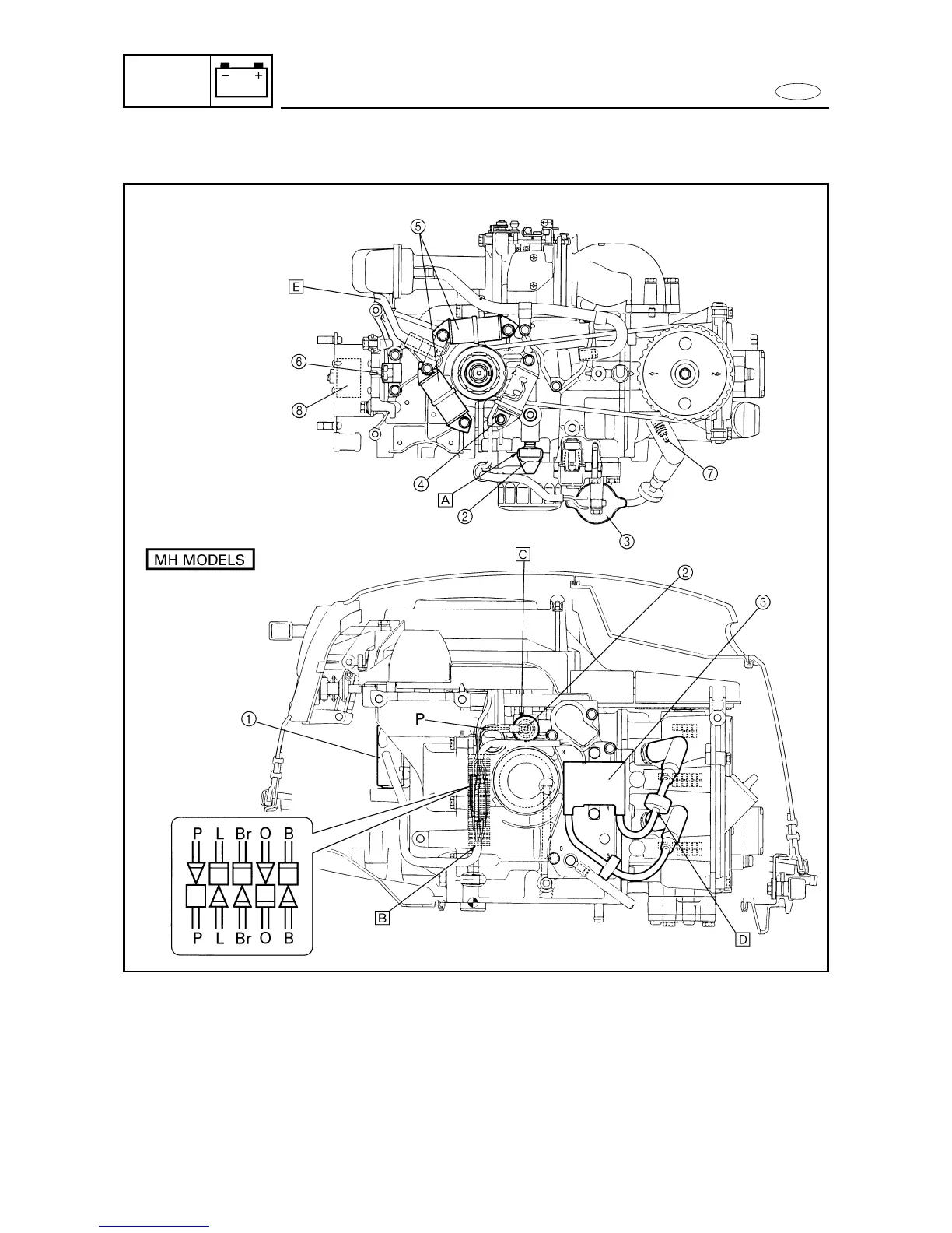
ELECTRICAL COMPONENTS
(Top view and port side view)
1 CDI unit
2 Oil pressure switch
3 Ignition coil
4 Charge coil
5 Lighting coil
6 Pulser coil
7 Spark plugs
8 Rectifier (marked 6G1)
Rectifier/regulator
(marked 6G8/6J8)
A Install the Pink lead onto the
oil pressure switch. Cover
the oil pressure switch after
tightening it.
B
Cover the oil pressure switch
lead, ignition coil lead and
charge coil lead with the cor-
rugated plastic tube after con-
necting the same color leads.
C Install the connector in the
proper direction as shown.
D Pass each high tension cord
through the grommet.
E Pass the lighting coil lead on
the side of the flywheel
cover, next to the boss as
shown.
8-1