E
ELECTRICAL ANALYSIS
ELEC
ELECTRICAL ANALYSIS
INSPECTION
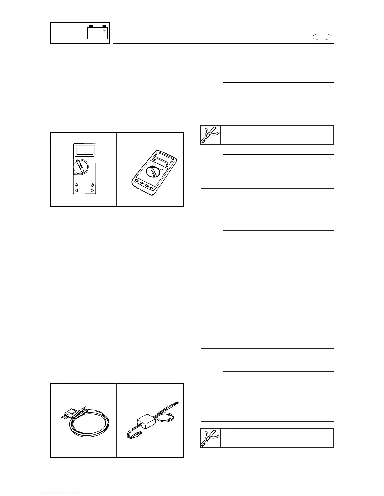
Digital circuit tester
NOTE:
Throughout this chapter the digital circuit
tester’s part number has been omitted.
Refer to the following part number.
NOTE:
"1
—
1" indicates a continuity of electrici-
ty; i.e., a closed circuit at the respective
switch position.
A For USA and CANADA
B Except for USA and CANADA
Peak voltage measurement
NOTE:
9 When checking the condition of the igni-
tion system it is vital to know the peak
voltage.
9 Cranking speed is dependant on many
factors (e.g., fouled or weak spark plugs,
a weak battery). If one of these is defect-
ed, the peak voltage will be lower than
specification.
9 If the peak voltage measurement is not
within specification the engine will not
operate properly.
9 A low peak voltage will also cause com-
ponents to prematurely wear.
Peak voltage adaptor
NOTE:
9 Throughout this chapter the peak voltage
adaptor’s part number has been omitted.
Refer to the following part number.
9 The peak voltage adaptor should be used
with the digital circuit tester.
A For USA and CANADA
B Except for USA and CANADA
8-9
Digitalcircuit tester:
J-39299/90890-06752
Peak voltage adaptor:
YU-39991/90890-03169
A B
A B



 To Next Page