E
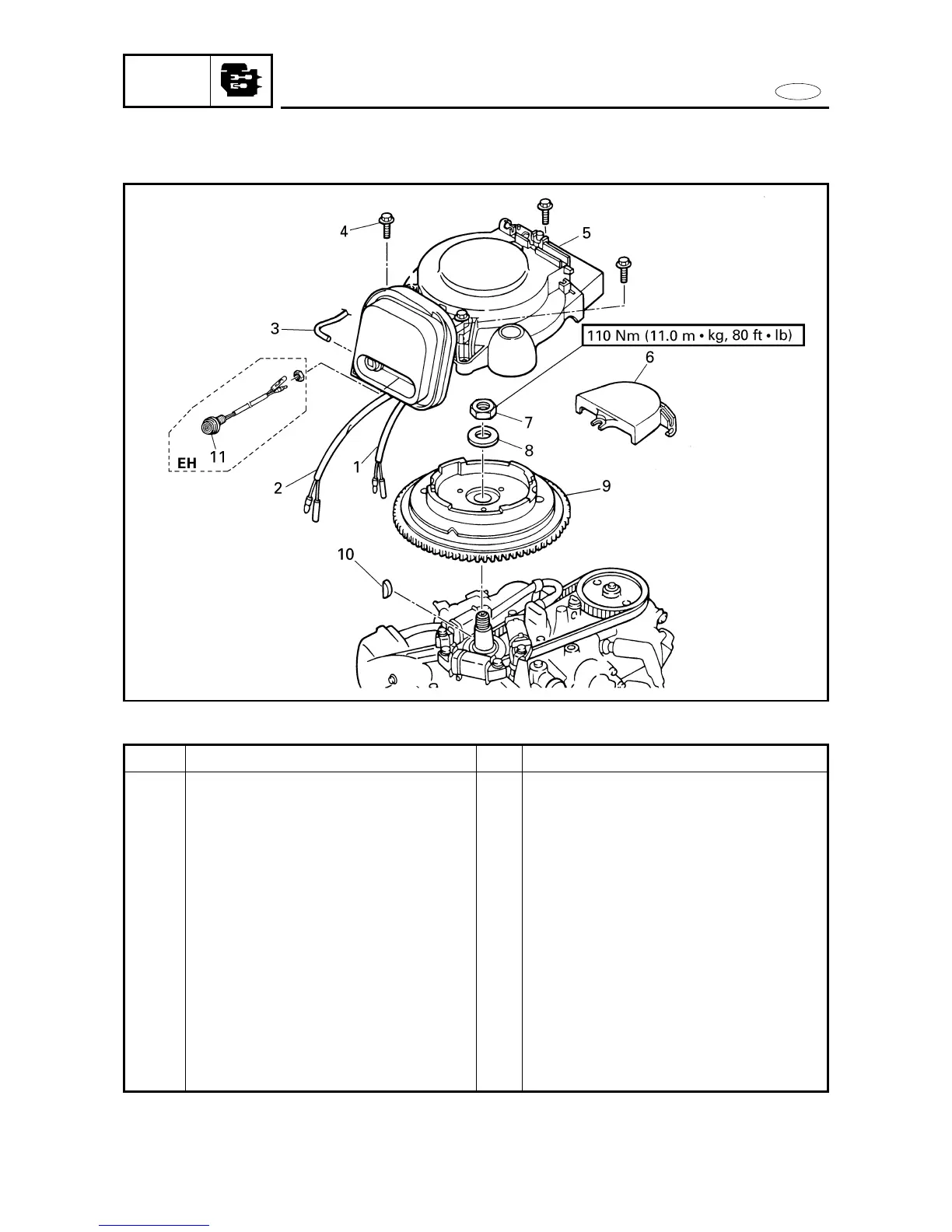
FLYWHEEL MAGNETO (EH/E MODELS)
POWR
FLYWHEEL MAGNETO (EH/E MODELS)
EXPLODED DIAGRAM
5-8
REMOVAL AND INSTALLATION CHART
Step
1
2
3
4
5
6
7
8
9
10
11
Q’ty
2
2
1
3
1
1
1
1
1
1
1
Service points
Follow the left ”Step” for removal.
At the battery side.
M6 x 25 mm
Reverse the removal steps for installation.
Procedure/Part name
FLYWHEEL MAGNETO REMOVAL
Battery cable
Low-oil-pressure warning indicator
lead
Starter switch lead (for EH models)
Choke rod
Bolt
Flywheel magneto cover
Driven sprocket cover
Nut
Washer
Flywheel magneto
Woodruff key
Starter switch (for EH models)