IGNITION SYSTEM PEAK VOLTAGE
w
When checking the CDI unit do not touch
any of the connections of the digital tester
lead wires.
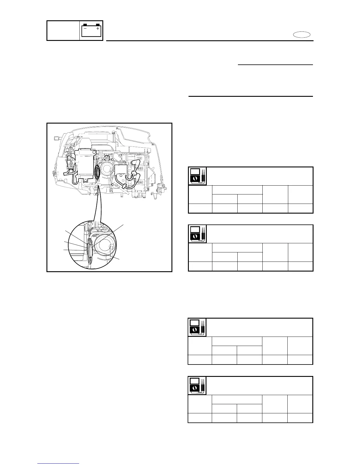
1. Measure:
9 CDI unit output peak voltage
Below specification → Replace the
ignition coil or check the CDI unit.
2. Measure:
9 Charge coil output peak voltage
Below specification → Replace the
charge coil.
8-13
Output peak voltage
O-B
r/min
Cranking
1,500 3,500
Opened Closed
V 120 115 160 160
Output peak voltage
O-B
r/min
Cranking
1,500 3,500
Opened Closed
V 120 120 160 160
Output peak voltage
Br-L
r/min
Cranking
1,500 3,500
Opened Closed
V 130 135 180 180
6 A model
6 A model
Output peak voltage
Br-L
r/min
Cranking
1,500 3,500
Opened Closed
V 130 135 180 180
10 A model
10 A model