E
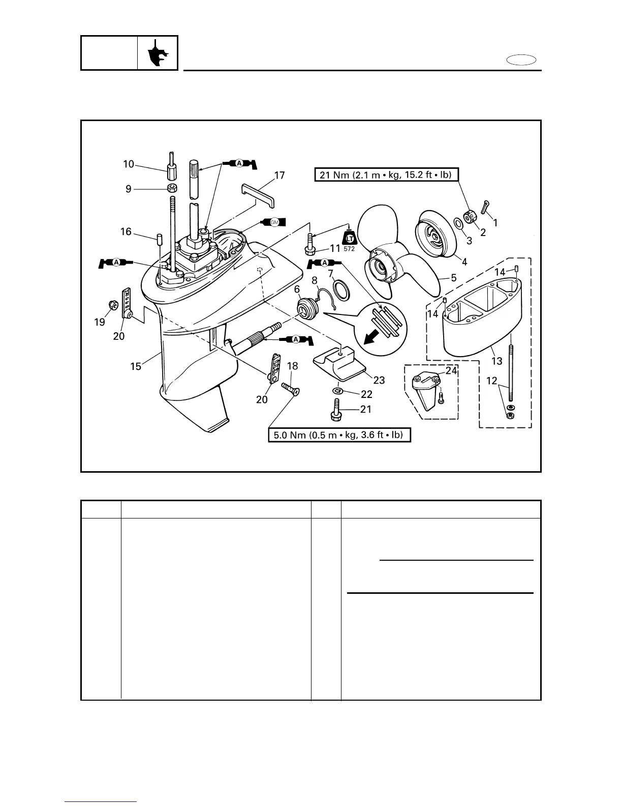
LOWER UNIT (FT9.9D)
LOWR
EXPLODED DIAGRAM
6-27
REMOVAL AND INSTALLATION CHART
Step
13
14
15
16
17
18
19
20
21
22
23
24
Q’ty
1
2
1
2
1
1
1
2
1
1
1
1
Service points
NOTE:
During installation, properly align the
drive shaft splines with the power unit.
Reverse the removal steps for installation.
Procedure/Part name
Extension (for X-transom models)
Dowel pin (for X-transom models)
Lower unit
Dowel pin
Rubber seal
Screw
Nut
Water inlet grill
Bolt
Toothed washer
Anode
Trim tab (for S-transom models)