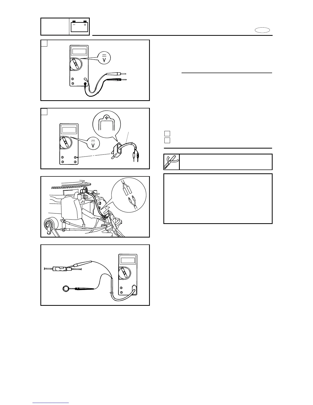
8 When measuring the peak voltage,
connect the peak voltage adaptor 1
to the digital tester and switch the
selector to the DC voltage mode.
NOTE:
9 Make sure the adaptor leads are properly
installed in the digital circuit tester.
9 Make sure the positive pin (the "+" mark
facing up as shown) on the adaptor is
installed into the positive terminal of the
tester.
9 The test harness is needed for the follow-
ing tests.
Voltage measurement
Peak voltage measurement
2
1
8-10
Checking steps:
8 Disconnect the connectors from the
pulser coil.
8 Connect the tester terminals to the
terminals which are being checked.
8 Start or crank the engine and observe
the measurement.
1
2
Peak voltage adaptor:
YU-39991/90890-03169
1