MACHINE INFORMATION 2
2-3
2. INTEGREX e-V
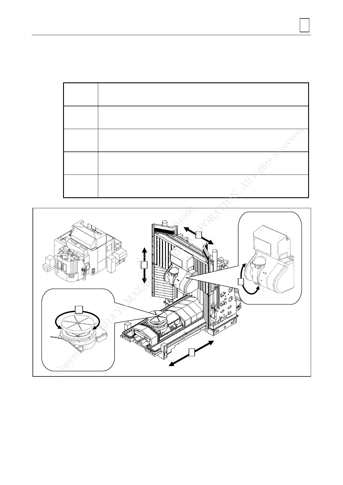
The axes of coordinates used for machine control are defined as follows:
Note: The axes of coordinates are defined with the operator standing and facing the front of
the machine.
Axis of transverse motion of the table
“+” (plus) indicates the leftward direction;
“-” (minus) indicates the rightward direction.
Axis of longitudinal motion of the milling spindle
“+” (plus) indicates the backward direction (to the rear);
“-” (minus) indicates the forward direction (to the front).
Axis of vertical motion of the milling headstock
“+” (plus) indicates the upward direction;
“-” (minus) indicates the downward direction.
Rotation of the milling spindle
“+” (plus) indicates the right-hand rotation (CW);
“-” (minus) indicates the left-hand rotation (CCW), as viewed from the operator door.
Rotation of the table
“+” (plus) indicates the right-hand rotation (CW);
“-” (minus) indicates the left-hand rotation (CCW), as viewed from above.
Rotation of the milling
spindle
Serial No. 294060
Copyright (c) 2013 YAMAZAKI MAZAK CORPORATION. All rights reserved.
 Loading...