SUPPLEMENT 5
5-49
10. G-code (Group12)
A. Selection of workpiece coordinate system
1. Command
Workpiece coordinate system 1
Workpiece coordinate system 2
Workpiece coordinate system 3
Workpiece coordinate system 4
Workpiece coordinate system 5
Workpiece coordinate system 6
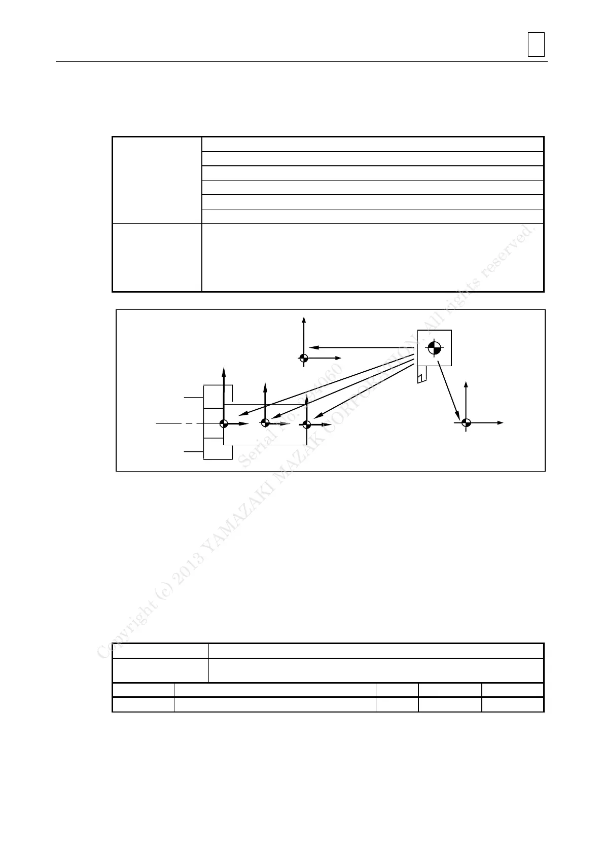
Commanding the above permits selection/change of one of six coordinate systems specified
beforehand that are agreed with the machine. By this command, subsequent axis commands
are used as positioning at selected workpiece coordinate system until the reset key is
pressed.
For the six workpiece coordinate systems, set the distance on each axis from the machine
zero point to the zero point of each coordinate system on the WORK OFFSET display.
2. Notes
The distance when coordinate system is moved by G92 is added subsequently to all
workpiece zero point offset values. For example, when coordinate system is moved by
“G92 X_ Z_” command in the selection of G54, G55 to G59 also move by the same
distance. Therefore, take care when having changed to G55.
The coordinate system cannot be established exactly for the C-axis by a command of
G54 to G59 if it is given with the C-axis not being connected. Do not fail, therefore, to
select the milling mode (for C-axis connection) before entering G54 to G59 as required
for the C-axis.
B. Additional workpiece coordinate system setting and selection
1. Command
In addition to the six standard systems G54 to G59, up to 300 sets of workpiece origin data
can be used to facilitate program creation.
Number of additional workpiece coordinate system
Serial No. 294060
Copyright (c) 2013 YAMAZAKI MAZAK CORPORATION. All rights reserved.
 Loading...