4 MACHINING PROGRAM
4-38
4-4-5 5-axis machining program
This section explains how to make the program of 5-axis machining.
1. 5-axis machining
This section explains how to make the general 5-axis machining.
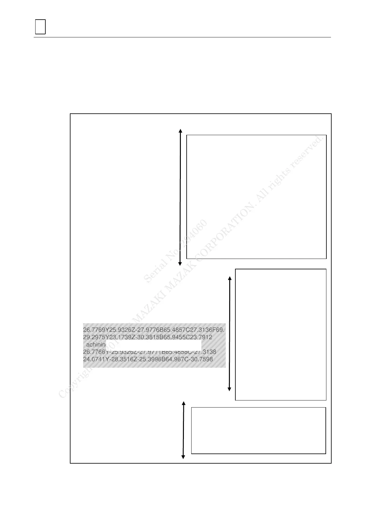
A. Sample program
G109L1
M901
M200
M212
G0G90G94G55G97
G40G49G80G67G69
G91G28X0
G28Z0
G28Y0
T001T00M06
G91G28X0
G28Y0
G28Z0
M108
G90G53B64.967
G97S12000M03
G10.9X0
M51
M821
G61.1
M108
G90G53B64.967
G90G00C30.759
G43.4G00X31.86Y32.98Z-21.168B64.967C30.759H1
G5P2
G01X24.0743Y28.3517Z-25.4001F104.
X26.7769Y25.9326Z-27.9776B65.4857C27.3136F69.
X29.2975Y23.1739Z-30.3815B65.9455C23.7912
(Machining contour)
X26.7766Y-25.9326Z-27.9771B65.4858C-27.3138
X24.0741Y-28.3516Z-25.3996B64.967C-30.7598
G00X31.8601Y-32.9856Z-21.1682
G5P0
G49
G64
M05
M09
G91G28X0
G28Z0
G28Y0
M108
G90G53B0
M30
Preparation motion for machining
G109L1: Upper turret selection
M901: HD1 spindle selection
M200: C-axis connect/Milling mode select
M212: C-axis unclamping
G94: Feed per minute
G97: Constant surface speed control OFF
T001M06: Tool change (TNo.01)
B-axis positioning
G97S12000: Rotation speed 12000 min
-1
M03: Forward milling spindle rotation
G10.9X0: Radius data input mode
M51: Milling spindle-through coolant ON
M821: Accuracy level 1
Machining motion
G61.1:
Geometry compensation
Rotational axis positioning
G43.4H**:
Tool tip point control
G5P2: High-speed
machining mode ON
(Machining pattern)
G5P0: High-speed
machining mode OFF
G49: Tool position
offset OFF
G64: Geometry
compensation OFF
End motion for machining
M05: Stop of milling spindle rotation
M09: Coolants OFF
Each axis positioning to zero return
M30: Reset and rewind
Serial No. 294060
Copyright (c) 2013 YAMAZAKI MAZAK CORPORATION. All rights reserved.
 Loading...