SUPPLEMENT 5
5-83
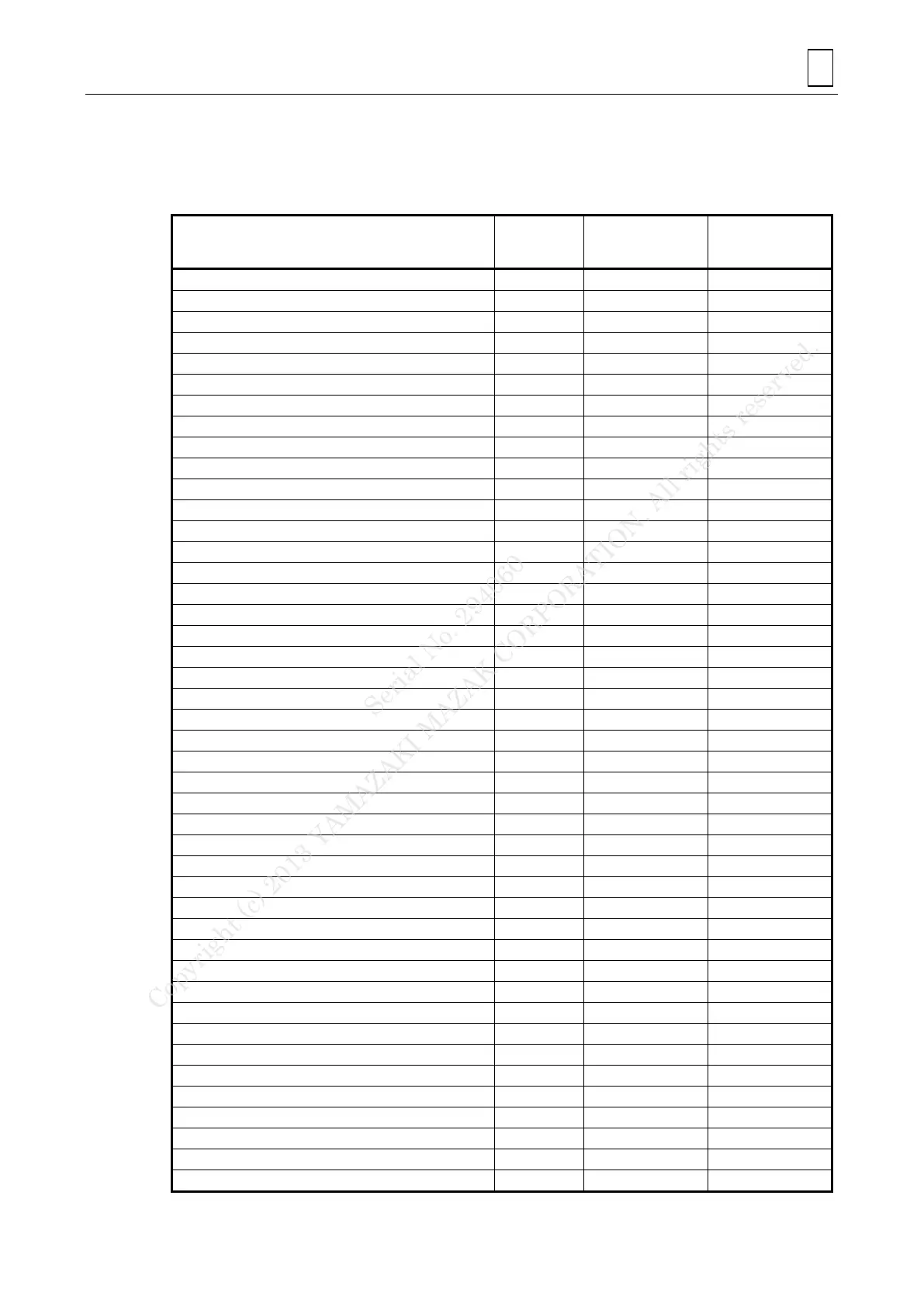
E. Combination of 3-D coordinate conversion (G68) and other function
The table below shows the modes in which 3-D coordinate conversion (G68) is selectable and
the selectable code in 3-D coordinate conversion.
: Selectable, -: Not selectable
G68 commanded
in leftward code
mode
Leftward code
commanded in
G68 mode.
Circular interpolation (CW)
Circular interpolation (CCW)
High-speed machining mode ON
High-speed machining mode OFF
Cylindrical Interpolation
Polar coordinate interpolation ON
Polar coordinate interpolation OFF
Return to Second Reference Point
Thread cutting (straight, taper)
Nose radius/Tool radius compensation OFF
Nose radius/Tool radius compensation (left)
Tool radius compensation for five-axis machining (left)
Nose radius/Tool radius compensation (right)
Tool radius compensation for five-axis machining (right)
Tool length offset in tool-axis direction
Tool tip point control (Type 1) ON
Tool tip point control (Type 2) ON
Coordinate system setting/Spindle speed range setting
Selection of machine coordinate system
Tool-axis direction control
Selection of workpiece coordinate system 1
Workpiece setup error correction
Selection of workpiece coordinate system 2
Selection of workpiece coordinate system 3
Selection of workpiece coordinate system 4
Selection of workpiece coordinate system 5
Selection of workpiece coordinate system 6
Selection of additional workpiece coordinate systems
High-accuracy mode (Geometry compensation)
3-D coordinate conversion ON
3-D coordinate conversion OFF
Inclined-plane machining ON
Serial No. 294060
Copyright (c) 2013 YAMAZAKI MAZAK CORPORATION. All rights reserved.
 Loading...