SUPPLEMENT 5
5-53
12. G-code (Group16)
A. Three-dimensional coordinate conversion
1. Command
The three-dimensional coordinate conversion is used to determine a new coordinate system
through the translation of the origin of the currently active workpiece coordinate system and
the rotation on an axis of coordinate. Use this command to specify freely a plane in space
which is convenient for programming.
Coordinates of the center of rotation
(X, Y, Z-axis)
±99999.9999 (mm)
±9999.99999 (in)
Designation of the axis of rotation (1: valid, 0: invalid)
I: X-axis
J: Y-axis
K: Z-axis
Angle and direction of rotation on the rotational axis.
(A positive value of angle refers to the left turn when
seen from the positive side of the rotational axis.)
2. Notes
An alarm occurs when a G68 command is given in the following modes.
Tool nose radius compensation (G40 mode not selected)
Fixed cycle (G80 not selected in the G-code group 09)
No tool change commands by T-code can be given in the G68 mode.
See “E. Combination of 3-D coordinate conversion (G68) and other function” in “5-3
Restriction of Combination”.
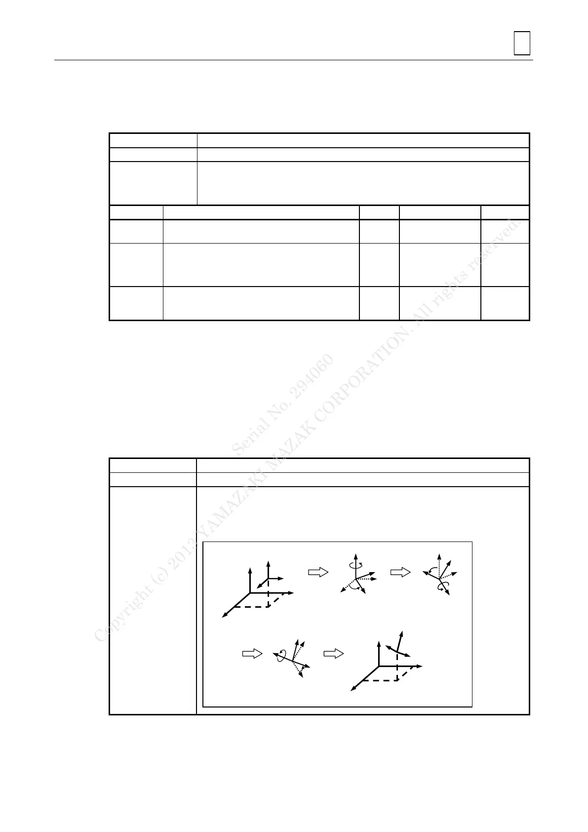
B. Inclined-plane machining
1. Command
G68.2 P0 Xx Yy Zz I J K
(Setting with Eulerian angles)
The inclined-plane machining function makes it possible to define a new coordinate system
(referred to as a feature coordinate system) by translating as well as rotating the current
workpiece coordinate system around the X-, Y- and Z-axis. Using this function, therefore, an
arbitrarily inclined plane can be defined in a space and the desired machining contour can be
programmed easily as if the plane concerned were an ordinary XY-plane.
Feature coordinate
system
Workpiece
coordinate
system
Workpiece
coordinate
system
Conversion by means of Eulerian angles
1) Translation of the
system
Serial No. 294060
Copyright (c) 2013 YAMAZAKI MAZAK CORPORATION. All rights reserved.
 Loading...