5 SUPPLEMENT
5-54
Coordinates of the origin of feature coordinate
system. To be specified with its absolute values in
the currently active workpiece coordinate system.
±99999.9999 (mm)
±9999.99999 (in)
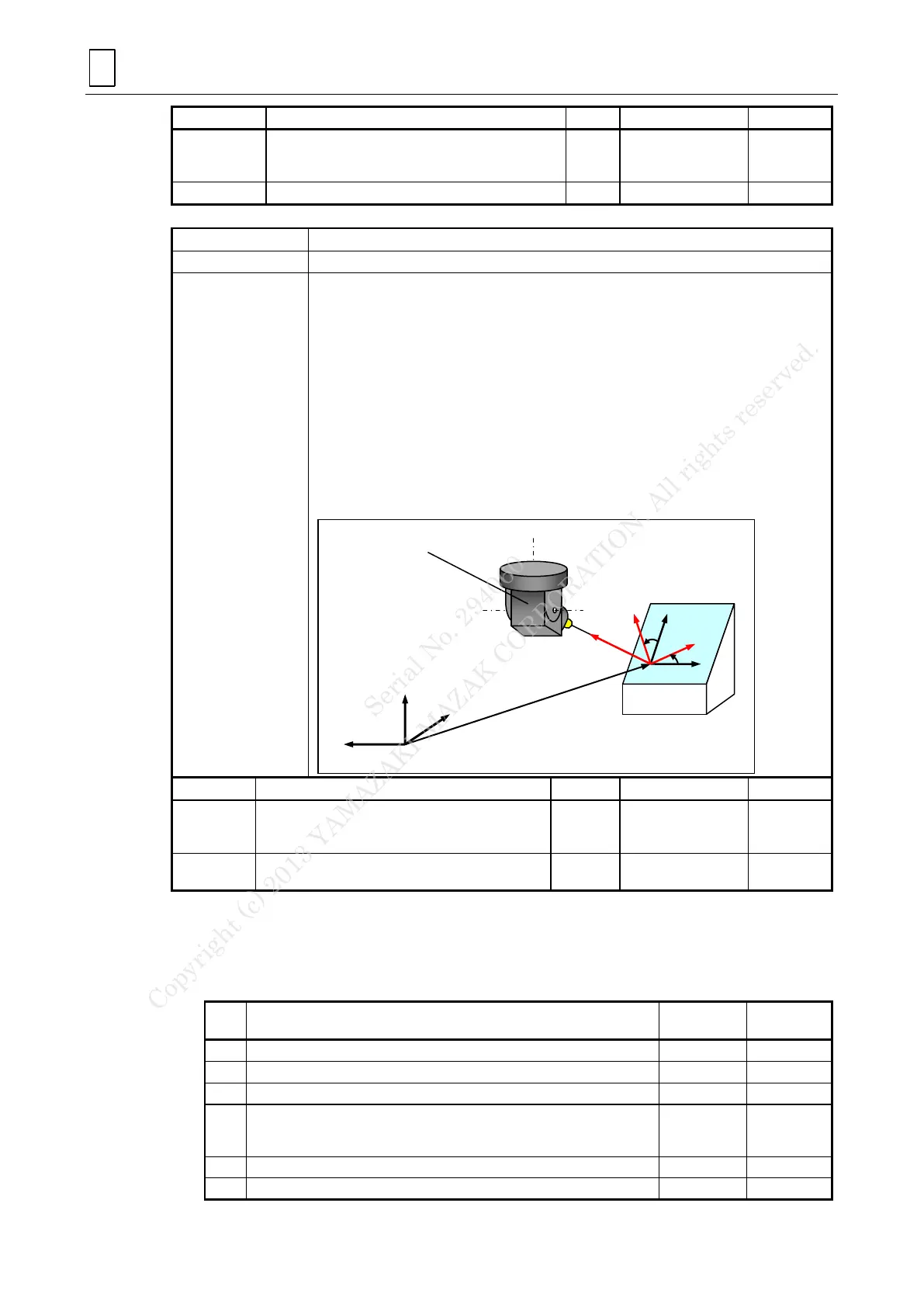
(Setting with tool-axis direction)
Point (x, y, z) in the current workpiece coordinate system is set as a new origin.
The feature coordinate system’s X-, Y-, and Z-axis are determined as follows.
The feature coordinate system’s Z-axis is set to be parallel with the current direction of
the tool axis.
The X-axis is inclined, with reference to the workpiece coordinate system, so as to
correspond with the angular positions of the tool. (The X-axis is, therefore, orientated in
parallel with the original one if the machine coordinates of the tool on its rotational axes
are 0°.)
The Y-axis is inclined, with reference to the workpiece coordinate system, so as to
correspond with the angular positions of the tool. (The Y-axis is, therefore, orientated in
parallel with the original one if the machine coordinates of the tool on its rotational axes
are 0°.)
Finally, the feature coordinate system is rotated around the Z-axis by an angle of °.
Coordinates of the origin of feature coordinate
system. To be specified with its absolute values in
the currently active workpiece coordinate system.
±99999.9999 (mm)
±9999.99999(in)
Angle of rotation around the Z-axis of the feature
coordinate system.
2. Notes
There are two programming types provided for inclined-plane machining (the selection
between which is to be done with parameter F34 bit 4): type A for combined use with
the other five-axis machining functions, and type B allowing various types of
interruption. This document mainly expounds upon Type A.
Combined use with the tool tip point control (G43.4/G43.5)
Combined use with the workpiece setup error correction (G54.4)
Combined use with the tool radius compensation for five-axis machining
Resumption of automatic operation after interruption without having
restored the positional conditions (in the use of manual interruption or
TPS function)
Changing the position on a rotational axis during interruption
Interruption using the manual pulse handle
Conversion by means of
tool axis direction
Workpiece coordinate system
1) Translation of the system
2) Orientation of the system
Serial No. 294060
Copyright (c) 2013 YAMAZAKI MAZAK CORPORATION. All rights reserved.
 Loading...