1 Outline
1.2.2 SERVOPACKs
1-6
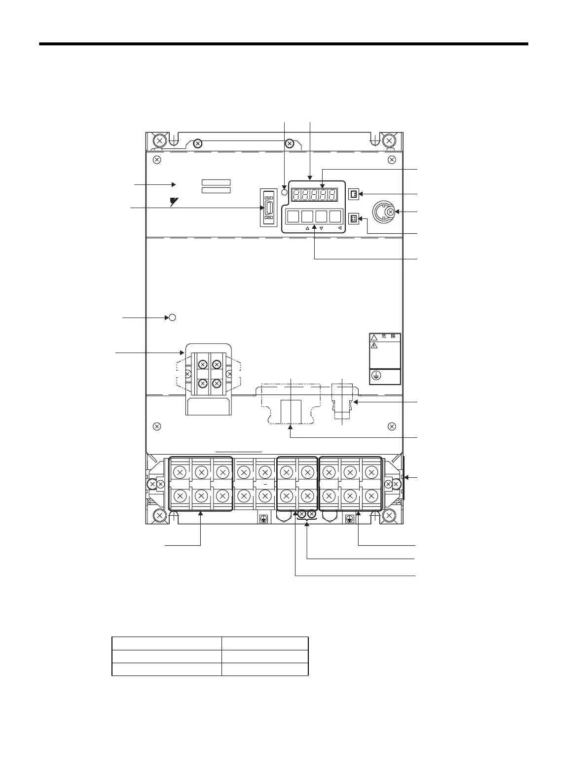
(2) SGDM for 6.0 kW to 15.0 kW
* Control circuit terminal and regenerative resistor connecting terminals differ the position of the terminal block by
the SERVOPACK model.
Refer to Chapter Chapter 4 SERVOPACK Specifications and Dimensional Drawings for details.
L1 L2 L3
U
B2B1
+
VW
!
WARNING
MODE/SET DATA/
Ve r.
POWER
BATTERY
CHARGE
SGDM-
SERVOPACK 200V
YASKAWA
Panel display
Power indicator
Panel operator
Charge indicator
L1C
CN1 CN2
L2C
Main circuit power supply
terminals: L1, L2, L3
Servomotor terminals: U, V, W
Regenerative resistor
connecting terminals: B1, B2
CN3 Connector for
personal computer
monitoring and
digital operator
CN8 Battery connector
CN5 Analog
monitor connector
Panel switch
Battery holder
Nameplate (side view)
CN2 Encoder connector
CN1 I/O signal connector
Control circuit
terminal
SERVOPACK model
Ground terminal
CN8
CN5
CN3
∗
∗
SERVOPACK Model Reference
SGDM-60ADA, 75ADA 4.7.7, 4.9.1
SGDM-1AADA, 1EADA 4.7.8, 4.9.2
Artisan Technology Group - Quality Instrumentation ... Guaranteed | (888) 88-SOURCE | www.artisantg.com
 Loading...


