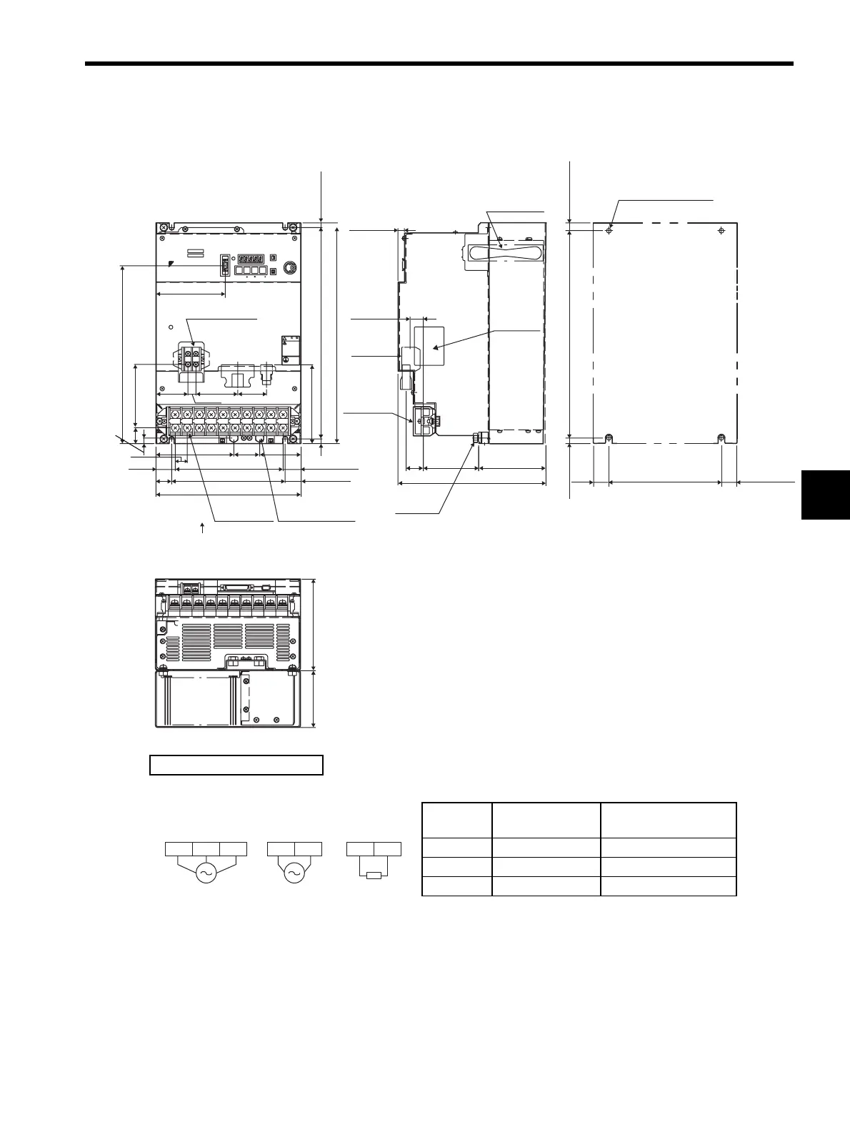
4.7 Dimensional Drawings of Base-mounted SERVOPACK Model
4-23
4
4.7.7 Three-phase 200 V: 6.0 kW/7.5 kW (60ADA to 75ADA)
Cooling fan
107 (4.21)
27
(1.06)
10 (0.39)
21 (0.83)
87.5 (3.44)
Main circuit
terminal
Control
circuit
terminal
Max. 235 (9.25)
25 (0.98)
28.3 (1.11)*
25 (0.98)*
30.5
(1.20)
171 (6.73)
180 (7.09)
Max. 230 (9.06)
25 (0.98)
9
(0.35)
41
(1.61)
123.5 (4.86)
(65.6)
19 (0.75)
Control circuit
terminal
M4
100.5 (3.96)
51
(2.01)
66
(2.60)
12.5 (0.49)
46
(1.81)
125 (4.92)
282.6 (11.13)
Main circuit
terminal M6
Max. 350 (13.78)
7.5
(0.30)
335 (13.19)
7.5 (0.30)
A
View A
L1 L2 L3
UB2B1+
-
VW
!WARNING
MODE/SET DATA /
Ve r.
POWER
BATTERY
CHARGE
CN2CN1
CN3
110 (4.33)
CN5
CN8
SGDM-
90 (3.54)
145 (5.71)
SERVOPARK 200V
YASKAWA
335 (13.19) 7.5 (0.30)
7.5 (0.30)*
180 (7.09)
25
(0.98)
25 (0.98)*
Ground terminal
M8
Nameplate
Mounting Hole Diagram
4×M6 screw holes
Ground
terminal
* Reference length
Units: mm (in)
Approx. mass: 14.3 kg (31.53 lb)
External Terminal Connector
SERVOPACK Connector
Connector
Symbol
SERVOPACK
Connector Model
Manufacturer
CN1 10250-52A2JL Sumitomo 3M Co., Ltd.
CN2 53460-0611 Molex Japan Co., Ltd.
CN3 10214-52A2JL Sumitomo 3M Co., Ltd.
L1C L2CL2 L3L1
External
regenerative
resistor
B1 B2
200 VAC
50/60 Hz
Three-phase
200 VAC
50/60 Hz
Single-phase
Main circuit
power supply
Control power
supply
Artisan Technology Group - Quality Instrumentation ... Guaranteed | (888) 88-SOURCE | www.artisantg.com
 Loading...


