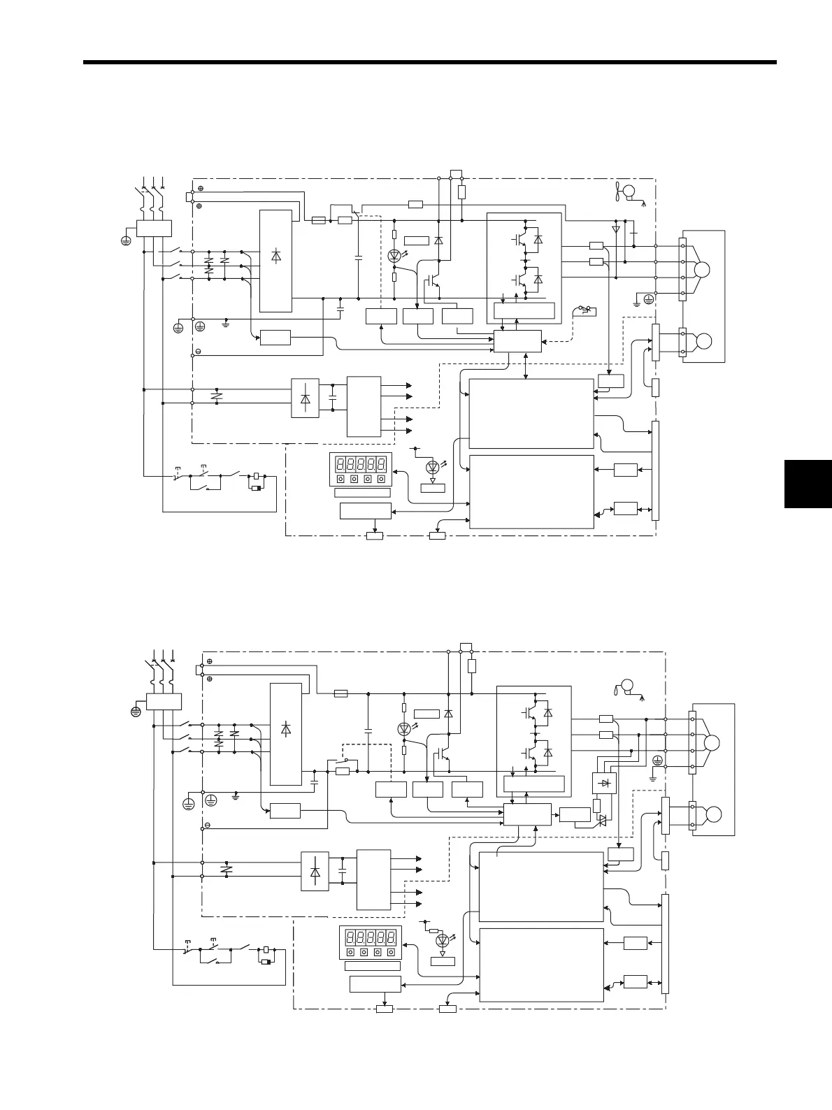
4.3 SERVOPACK Internal Block Diagrams
4-9
4
4.3.2 Three-phase 200 V, 500 W to 1.5 kW Models
4.3.3 Three-phase 200 V, 2.0 kW to 5.0 kW Models
THS1
R2
FU1
FAN1
±12V
1
2
1KM
L1
L3
L2
XX1
XX2
XX3
L1C
L2C
R
T
P
N
S
~
~
+
-
+
-
C1
RY1
+
-
CHARGE
B1 B2 B3
P
N
POWER
+5 V
0 V
CN5
CN3
+15 V
±5 V
+5 V
±12 V
U
V
W
A/D
I/O
CN1
CN2
PG
M
CN8
D2 D3 D4
U
V
W
1KM
1KM
1KM
PG output
Reference pulse input
Speed/torque
reference input
Sequence I/O
∗ When 0.5 kW to 1.0 kW
models are used.
Single/Three-phase 200 to 230 V
(50/60 Hz)
+10%
-15%
Noise
filter
Voltage
sensor
Relay
drive
Gate
drive
Voltage
sensor
Gate drive over-
current protector
Interface
Current
sensor
Servomotor
Power
OFF
Power
ON
Open during
servo alarm (1RY)
Surge
suppressor
Analog voltage
converter
Panel operator
Analog monitor
output for
supervision
Digital operator or
personal computer
CPU
(Position/speed
calculation, etc.)
ASIC
(PWM control, etc.)
For battery connection
DC / DC
converter
~~~
DB
1
2
1KM
L1
L3
L2
XX1
XX2
XX3
L1C
L2C
1KM
FU1
C1
RY1
+
-
+
-
+
-
+5 V
0 V
CN5
CN3
+15 V
±5 V
+5 V
±12 V
B1 B2 B3
P
N
+
-
FAN1
±12 V
U
V
W
I/O
A/D
CN1
CN2
PG
M
CN8
1KM
1KM
1RY
PG output
Reference pulse input
Speed/torque
reference input
Sequence I/O
R
T
P
N
S
+
-
~
~
POWER
CHARGE
N
U
V
W
CN2
Three-phase 200 to 230 V
(50/60 Hz)
+10%
-15%
Noise
filter
Voltage
sensor
Relay
drive
Gate
drive
Voltage
sensor
Gate drive over-
current protector
Interface
Current
sensor
Servomotor
Gate
drive
For battery connection
Analog voltage
converter
Panel operator
Analog monitor
output for
supervision
Digital operator or
personal computer
CPU
(Position/speed
calculation, etc.)
ASIC
(PWM control, etc.)
Power
OFF
Power
ON
Open during
servo alarm (1RY)
Surge
suppressor
DC / DC
converter
Artisan Technology Group - Quality Instrumentation ... Guaranteed | (888) 88-SOURCE | www.artisantg.com
 Loading...


