8.5 Operating Using Speed Control with Analog Reference
8-45
8
8.5.7 Encoder Signal Output
Encoder feedback pulses processed inside the SERVOPACK can be output externally.
The following signals are added when using an absolute encoder.
* SG (CN1-1, 2): Connect to 0 V on the host controller.
Dividing
The dividing means that the divider converts data into the pulse density based on the pulse data of the encoder installed on
the servomotor, and outputs it. The setting unit is the number of pulses/revolution.
Type Signal
Name
Connector
Pin Number
Name
Output PAO CN1-33 Encoder output phase A
/PAO CN1-34 Encoder output phase /A
Output PBO CN1-35 Encoder output phase B
/PBO CN1-36 Encoder output phase /B
Output PCO CN1-19 Encoder output phase C (zero-point pulse)
/PCO CN1-20 Encoder output phase /C (zero-point pulse)
* The pulse width of the zero-point pulse (phase C) is changed according to the setting of the dividing ratio (Pn201). This
pulse width should be the same as that for phase A.
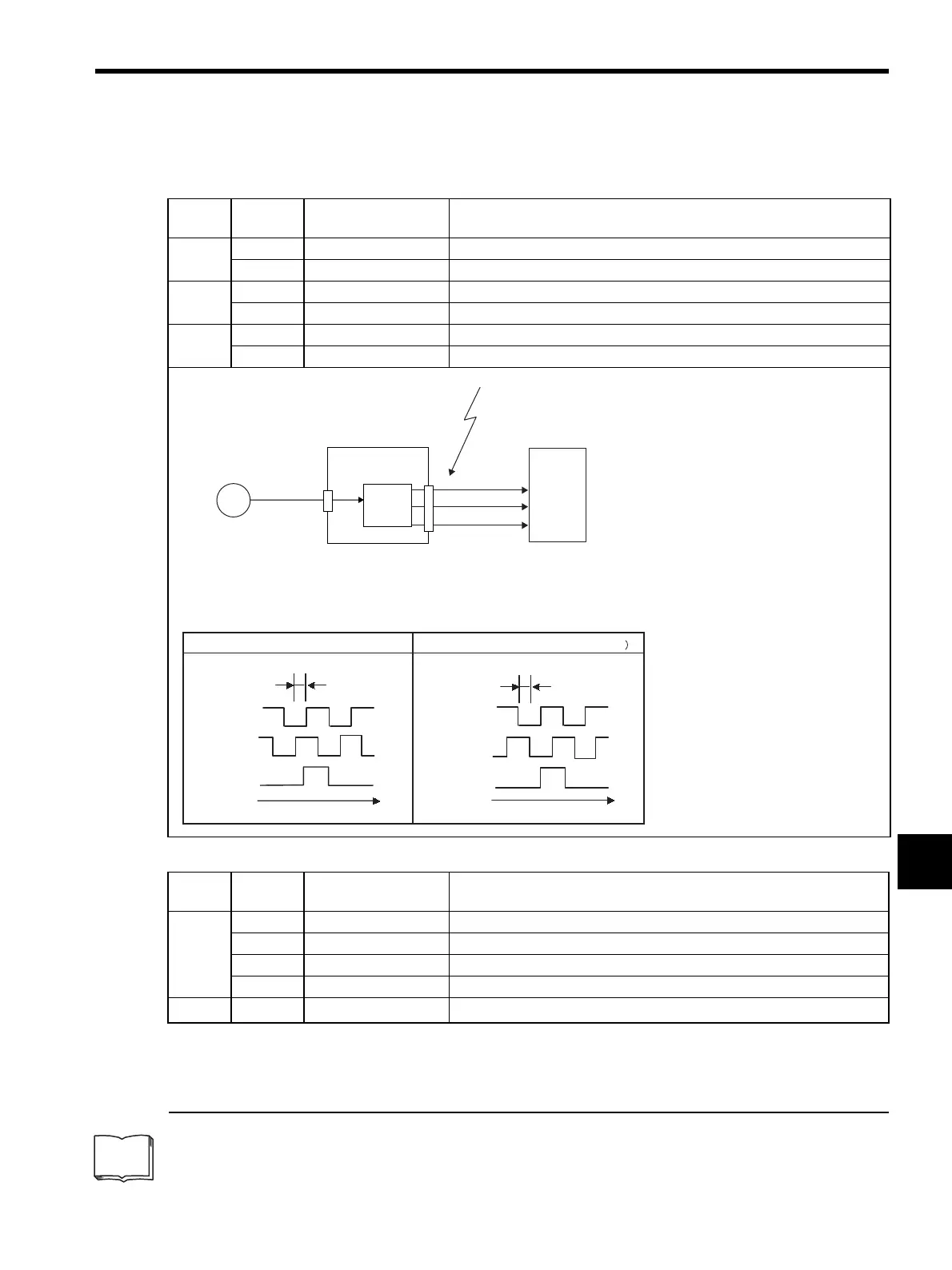
Output Phase Form
PG
SERVOPACK
CN2
CN1
(Servomotor)
Encoder
Host controller
These outputs explained here.
Phase A (PAO)
Phase B (PBO)
Phase C (PCO)
Serial data
Frequency
dividing
circuit
*
Phase A
Phase B
Phase C
90
˚
t
Phase A
Phase B
Phase C
90˚
t
Forward rotation (phase B leads by 90˚) Reverse rotation (phase A leads by 90˚
Type Signal
Name
Connector
Pin Number
Name
Input SEN CN1-4 SEN Signal Input
SG CN1-2 Signal Ground
BAT (+) CN1-21 Battery (+)
BAT (-) CN1-22 Battery (-)
Output
SG
∗
CN1-1 Signal Ground
TERMS
Artisan Technology Group - Quality Instrumentation ... Guaranteed | (888) 88-SOURCE | www.artisantg.com
 Loading...


