4 SERVOPACK Specifications and Dimensional Drawings
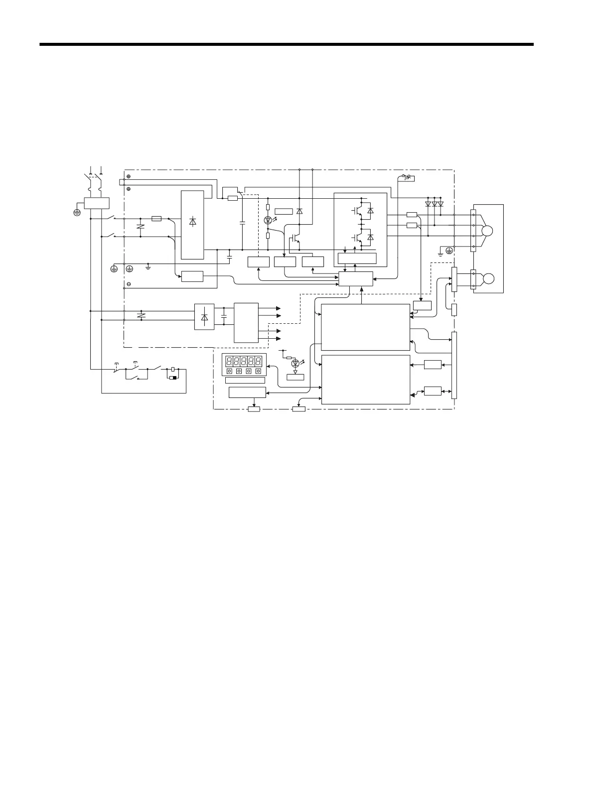
4.3.1 Single-phase 200 V, 30 W to 400 W, and 100 V, 30 W to 200 W Models
4-8
4.3 SERVOPACK Internal Block Diagrams
4.3.1 Single-phase 200 V, 30 W to 400 W, and 100 V, 30 W to 200 W Models
CHARGE
POWER
A/D
I/O
1KM
L1
L2
XX1
FU1
L1C
L2C
1KM
~
~
+
-
R
T
N1
TR1
C1
+5 V
0 V
CN5
CN3
+15 V
B1 B2
P2
N2
U
V
W
CN1
CN2
D2 D3 D4
THS1
PG
M
R7
R8
±5 V
+5 V
±12 V
CN8
1
PM1-1
D1
RY1
PM1-2
2
+
-
+
-
U
V
W
1KM
1RY
Reference pulse input
Speed/torque
reference input
Sequence I/O
Single-phase 200 to 230 V
(50/60 Hz)
+10%
-15%
+10%
-15%
Single-phase 100 to 115 V
Noise
filter
Voltage
sensor
Power
OFF
Power
ON
Open during
servo alarm (1RY)
Surge
suppressor
∗ The supply voltage for 100V, 30 to 200W is 100 to 115V (50/60 Hz).
Relay
drive
Gate
drive
Voltage
sensor
Gate drive over-
current protector
Interface
Current
sensor
Servomotor
Analog voltage
converter
Panel operator
Analog monitor
output for
supervision
Digital operator or
personal computer
CPU
(Position/speed
calculation, etc.)
ASIC
(PWM control, etc.)
PG output
For battery connection
DC / DC
converter
+10%
-15%
Artisan Technology Group - Quality Instrumentation ... Guaranteed | (888) 88-SOURCE | www.artisantg.com
 Loading...


