6 Wiring
6.2.2 Encoder Connector (CN2) Terminal Layout
6-8
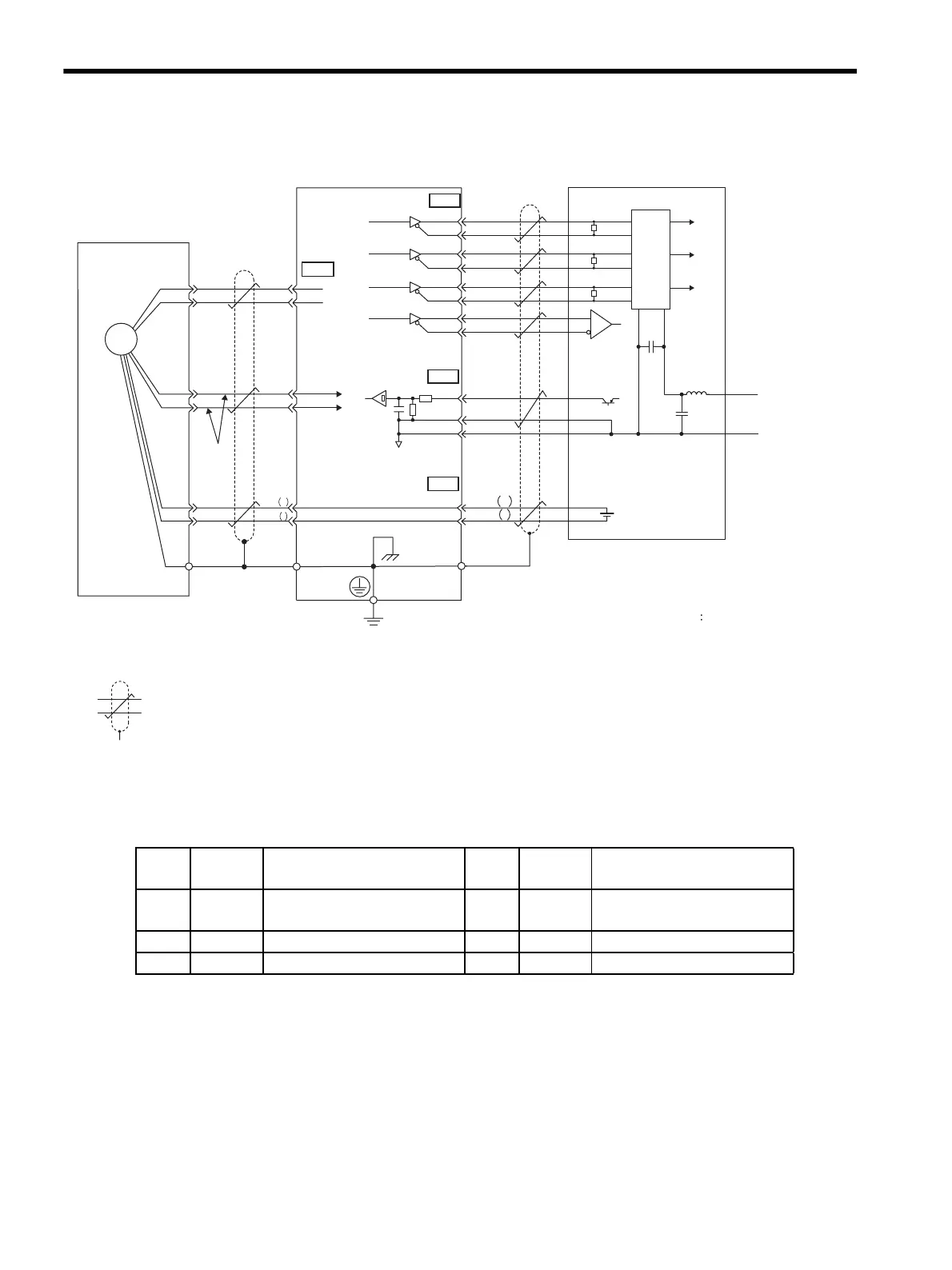
(2) Absolute Encoders
6.2.2 Encoder Connector (CN2) Terminal Layout
Absolute encoder
SERVOPACK
: represents twisted-pair wires.
When using an absolute encoder, install a battery on the host controller side to
supply power.
∗3
The pin numbers for the connector wiring differ depending on the servomotors.
C,D,H,G,S,T : pin number for the SGMGH, SGMSH, SGMDH servomotors.
1, 2, 3, 4, 5, 6 : pin number for the SGMAH and SGMPH servomotors
∗1
∗2
Line receiver
Host controller
/PCO
PG
3
4
4
2
SG
SEN
21
22
BAT
BAT
+
-
CN2
33
34
35
36
19
20
48
49
CN1
0 V
SG
1
PG5 V
PG0 V
PA
O
/P
AO
PBO
/PBO
PCO
/PSO
PSO
0.33 mm
2
CN1
CN1
∗2
∗3
∗2
∗1
0 V
0 V
+5 V
+5 V
+5 V
11
5
3
2
1
R
6
7
10
9
816
C
+
-
R
R
+
-
5
6
1
2
PG5V
PG0V
PS
/PS
BAT +
BAT -
C (5)
D (6)
H (1)
G (2)
T (3)
S (4)
Shield wire
Orange
White/Orange
(Shell)
Connector
shell
Connector
shell
Applicable line receiver: SN75175 manufactured
by Texas Instruments or the
equivalent corresponding to MC3486.
R (terminator): 220 to 470 Ω
C (Decoupling Capacitor)
0.1 µF
Battery
Phase A
Phase B
Phase C
Phase
A
Phase
B
Phase
C
Phase S
Choke
coil
Smoothing
capacitor
(0.001in
2
)
J
Light
blue
White/Light blue
Red
Black
Output line-driver SN75ALS194
manufactured by Texas
Instruments or the equivalent.
1
PG5V
PG power supply
+5 V
2
PG 0 V
PG power supply
0 V
3
BAT (+)
Battery (+)
(For an absolute encoder)
4
BAT (-)
Battery (-)
(For an absolute encoder)
5
PS PG serial signal input
6
/PS PG serial signal input
SHELL
Shield −
−
−−
Artisan Technology Group - Quality Instrumentation ... Guaranteed | (888) 88-SOURCE | www.artisantg.com
 Loading...


