4.7 Dimensional Drawings of Base-mounted SERVOPACK Model
4-19
4
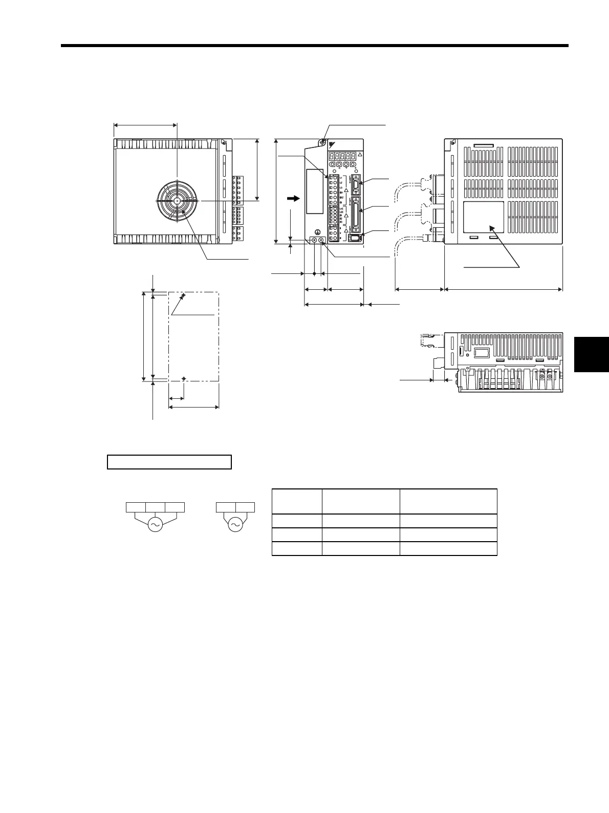
4.7.3 Three-phase 200 V: 500 W/750 W/1.0 kW (05AD to 10AD, 05ADA to 10ADA)
90 (3.54)
27 (1.06)
149.5±0.5 (5.87±0.02)
5 (0.20)*
2×M4 screw
holes
(Mounting pitch)
Mounting Hole Diagram
CN3
160 (6.30)
5.5
(0.22)
96.2 (3.79)
10 (0.39)
55 (2.17)
CN2
CN1
YASKAWA SERVOPACK200V
SGDM-
MODE/SET
CHARGE POWER
DATA/
YASKAWA
94.4 (3.72)
5 (0.20)
160 (6.30)
15 (0.59)
Cooling fan
φ5 (φ0.20) hole
Terminal
block
35
(1.38)
90 (3.54)
75 (2.95)*
8 (0.31)
Ground terminal
2×M4 screws
Nameplate
17 (0.67)
* Reference length
Units: mm (in)
Approx. mass: 1.7 kg (3.75 lb)
180 (7.09)
External Terminal Connector
SERVOPACK Connector
Connector
Symbol
SERVOPACK
Connector Model
Manufacturer
CN1 10250-52A2JL Sumitomo 3M Co., Ltd.
CN2 53460-0611 Molex Japan Co., Ltd.
CN3 10214-52A2JL Sumitomo 3M Co., Ltd.
Three-phase
200 VAC
50/60 Hz
Single-phase
200 VAC
50/60 Hz
L2 L3L1 L1C L2C
Main circuit
power supply
Control power
supply
Artisan Technology Group - Quality Instrumentation ... Guaranteed | (888) 88-SOURCE | www.artisantg.com
 Loading...


