7-19
IM 760201-01E
Waveform Display
3
2
1
4
5
6
7
8
9
10
11
12
13
14
App
Index
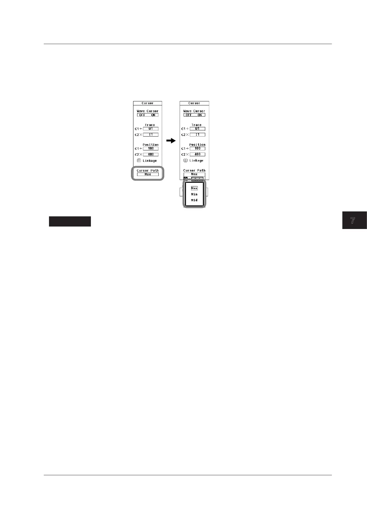
Selecting a Cursor Path
14.
Use the cursor keys to select Cursor Path.
15.
Press SET to display the cursor path selection box.
16.
Use the cursor keys to select one of the options from Max to Mid.
17.
Press SET to confirm the selection.
Explanation
For an explanation of the cursor measurement feature itself, see section 2.7.
Turning Cursor Measurement On or Off
A cursor can be placed on the displayed waveform, and the value at the cursor location
can be measured and displayed. The voltage or current at specific sections of the
waveform and the data on the horizontal axis (X-axis) can be measured.
•
ON: Cursor measurement is performed.
• OFF: Cursor measurement is not performed.
Selecting the Waveform to Measure
You can select the waveform to measure using cursors from one of the choices below.
The selectable items vary depending on the number of elements installed in the WT500.
U1, I1, U2, I2, U3, and I3
Measurable Items
• Y+: Vertical value of cursor + (Y-axis value)
• Yx: Vertical value of cursor x (Y-axis value)
•
Δ
Y
: The difference between the Y-axis values of cursor + and cursor x
• X+: X-axis value of cursor + from the left edge of the screen
• Xx: X-axis value of cursor x from the left edge of the screen
•
Δ
X:
The difference between the X-axis values of cursor + and cursor x
• 1/
Δ
X:
Reciprocal of the difference between the X-axis values of cursor + and cursor x
7.9 Measuring with Cursors

 Loading...


