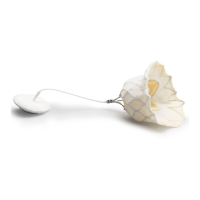
Closure
The closure creates an airght seal necessary for proper uid movement within the cartridge. The
closure also ensures that calibrant and sample remain contained within the cartridge during the tesng
cycle and subsequent disposal.
Cartridge on the le in the illustraon contains natural rubber latex on the snap closure. The cartridge
shown on the right is not made with natural rubber latex.
Heang elements
All i‑STAT cartridges require thermal control at 37°C (98.6°F), and include heang elements on the
underside of the sensor chips which are contacted and heated by the instrument's thermal probes.
Standardizaon and calibraon
Standardizaon is the process by which a manufacturer establishes “true” values for representave
samples. A mul-point calibraon curve, the slope or sensivity of which is dened by coecients in the
CLEW soware, is derived for each sensor by this standardizaon process. These calibraon curves are
stable over many lots.
A one-point calibraon is performed each me a cartridge requiring calibraon is used. During the rst
part of the tesng cycle, the calibrant soluon is automacally released from its foil pack and is
posioned over the sensors. The signals produced by the sensors’ responses to the calibrant soluon are
measured. This one-point calibraon adjusts the oset of the stored calibraon curve. Next, the
instrument automacally moves the sample over the sensors and the signals produced by the sensors’
responses to the sample are measured. While coecients are used rather than graphic calibraon
curves, the calculaon of the result is equivalent to reading the sample’s concentraon from an adjusted
calibraon curve.
Types of cartridge sensors
Sensors are thin lm electrodes microfabricated onto silicon chips. Sensing funconality is imparted to
each electrode by a number of chemically sensive lms coated over the acve region of the electrodes.
The cartridges have three dierent types of sensors built in: potenometric, amperometric, and
conductometric.
Potenometric sensors
In potenometric measurements, the dierence in potenal that exists between an indicator
electrode and a reference electrode is measured. Ion-selecve electrodes (ISE) are examples of
potenometric sensors. The indicator electrode is designed to be sensive to a parcular ion in a
soluon. In cases where other ions are sensed by the system, selecvity coecients can be used
to correct for this interference. An enzyme can be added to an ISE to produce ions from analytes
of interest that are not themselves ions.
Potenometric sensors ulize two important concepts. The rst concept is the Nernst Equaon
which relates the measured potenal to the acvity of the ion being measured. It is wrien as:
E = E° + RT/nF ln a
91
i-STAT Alinity — System Operaons Manual Art: 745524-01 Rev. I Rev. Date: 02-Nov-2022