Version 16.10 AF-6600 AF-5000 Series Install Manual 102
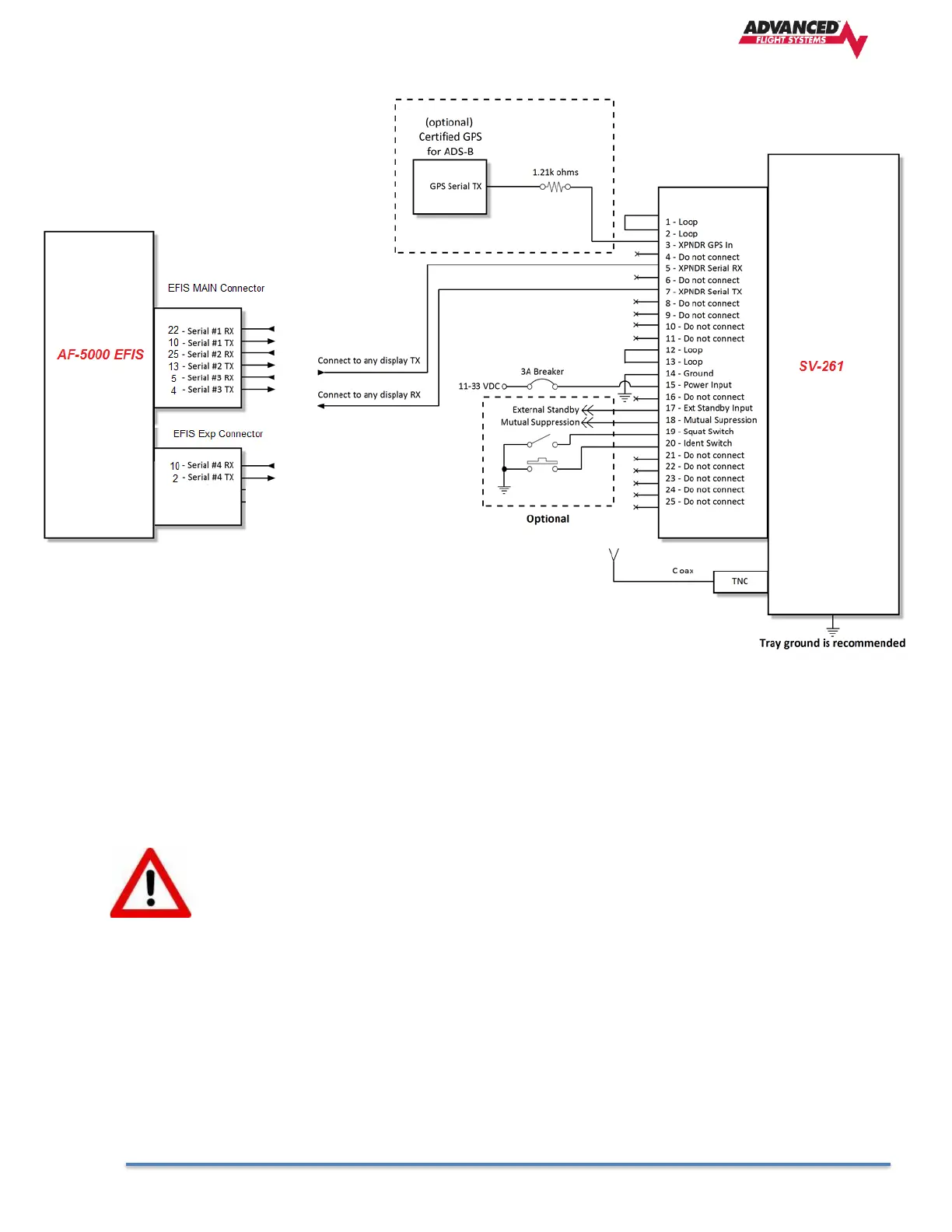
Note that pins 1 <> 2, and pins 12 <> 13 must be connected to each other as depicted above via your wiring harness.
They are not shorted internally.
Power/Ground Input
The power supply can be 11-33 Volts DC; no voltage adjustment is required. 20 AWG wire is sufficient for wire runs up
to 50’ for this application. Use a 3 or 5 Amp fuse or circuit breaker for power supply protection to the SV-261.
The transponder power input is not protected against reversed power connections. Reversing the
power and ground inputs to the transponder will destroy it. Check wiring before applying power.
Mutual Suppression (optional)
Mutual Suppression allows two or more transmitters on adjacent frequencies to inhibit the other transmitters when
one is active to limit the interference effects. It is commonly used between transponders and DME systems, and
between transponders and collision avoidance systems. Most installations will not make use of this feature, since most
AF-5000 equipped aircraft have only one transponder and often do not have DME equipment or other active traffic
system that interrogate other aircraft.
The Mutual Suppression pin (18) is an ARINC compatible suppression bus interface, which acts as both an input and an
output. The SV- 261 will assert this signal when it is transmitting, and can be suppressed by other equipment that
asserts the signal. The SV -261 will drive approximately 24 Volts on the output (independently of supply voltage), and
will treat the input as active whenever the bus has greater than 10 Volts. If you are using the Mutual Suppression
feature, simply connect all of the Mutual Suppression wires from devices that use them together.